Isolated switching power supply apparatus

a power supply apparatus and isolation technology, applied in the direction of power conversion systems, dc-dc conversion, instruments, etc., can solve the problems of large dependence of inability to use general hysteresis control methods in applications, and large general hysteresis control methods, so as to achieve high-stable output voltage control, reduce forward loss, and enhance circuit efficiency

Active Publication Date: 2011-12-01
MURATA MFG CO LTD
View PDF7 Cites 13 Cited by
  • Summary
  • Abstract
  • Description
  • Claims
  • Application Information

AI Technical Summary

Benefits of technology

[0018]Accordingly, preferred embodiments of the present invention provide an isolated switching power supply apparatus in which an ON / OFF type isolated DC-DC converter storing electromagnetic energy in a main transformer during an ON period of a power switch and releasing the electromagnetic energy to an output during an OFF period of the power switch does not use a photocoupler for which the allowable temperature range is relatively narrow and the current transfer ratio changes over time, performs high-speed, highly stable output voltage control, and further allows zero voltage switching of the power switch to reduce switching loss and noise.

Problems solved by technology

On the other hand, a general hysteresis control method has a disadvantage in that the general hysteresis control method is greatly dependent on ripples caused by a switching operation.
In addition, when ripples are too small, the control may become unstable due to the influence of noise, and as a result, the general hysteresis control method cannot be used in applications that require ripples to be of a strict standard value.
Furthermore, when a low ESR capacitor such as a ceramic capacitor is used as an output smoothing capacitor, a ripple has a voltage waveform that is close to a sinusoidal wave pattern having a π / 2 phase delay, rather than a ramp wave pattern, and thus the gain is reversed at the beginning of an ON period of a power switch (that is, at the time when the power switch is turned ON, the output voltage on the secondary side is changed to a falling direction), and thereby stable control cannot be performed.
The Bang-Bang control has an advantage in that there is an improved transient responsiveness but the Bang-Bang control has the same problem as the hysteresis control method, which is the disadvantage of being greatly dependent on ripples in a switching operation.
Since the ripple voltage in the output smoothing capacitor decreases during the ON period and increases during the OFF period, the gain is reversed in the hysteresis control method and the Bang-Bang control method, and thereby stable control cannot be performed.
That is, because there is a relationship where the output voltage on the secondary side of the main transformer decreases during an ON period of the power switch, the control direction is inverted, and thereby control becomes difficult.
For these reasons, there is a problem in that the hysteresis control method and the Band-Band control method cannot be applied to ON / OFF type isolated DC-DC converters.
Furthermore, feedback control in a voltage mode and a current mode, which are general modes in ON / OFF type isolated DC-DC converters, has many problems such as an inferior response compared to that in the hysteresis control method and the Bang-Bang control method, and a photocoupler used in transmission of error signals from the secondary side to the primary side, having pronounced transmission delay of signals, limitation of the maximum allowable temperature to approximately 100° C., and a current transfer ratio that changes over time.
However, since the hysteresis control method and the Bang-Bang control method determine the turn ON timing of the power switch by comparing the output voltage with the reference voltage, zero voltage switching cannot be realized in an ON / OFF type DC-DC converter, even if the hysteresis control method or the Bang-Bang control method can be applied thereto.
As a result, there is a problem that causes an increase in switching loss and noise.

Method used


Image

  • Isolated switching power supply apparatus
  • Isolated switching power supply apparatus
  • Isolated switching power supply apparatus

Examples


first preferred embodiment

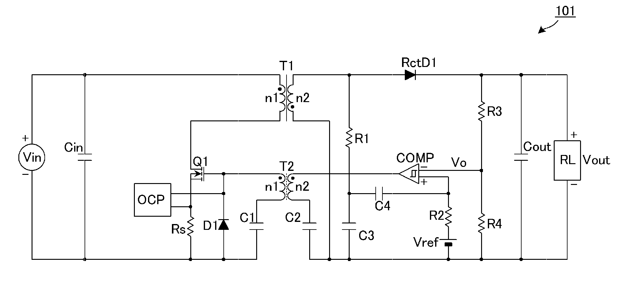
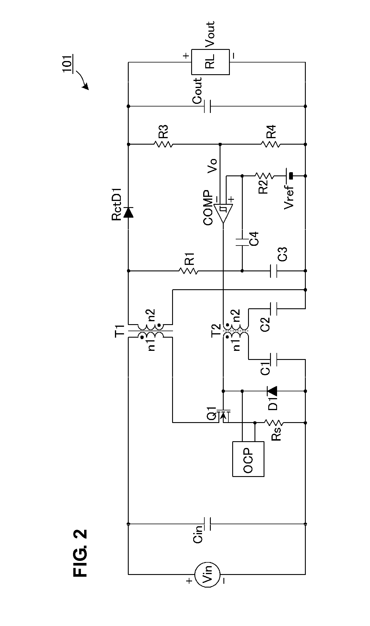
[0052]FIG. 2 is a circuit diagram of an isolated switching power supply apparatus 101 according to a first preferred embodiment. FIGS. 3A-3I are waveform diagrams for each section thereof.

[0053]The isolated switching power supply apparatus 101 in FIG. 2 preferably is an ON / OFF type isolated DC-DC converter (flyback DC-DC converter), for example. The isolated switching power supply apparatus 101 is connected to a DC input power supply Vin and supplies a predetermined constant voltage to a load RL.

[0054]A power converting section of the isolated switching power supply apparatus 101 includes an input smoothing capacitor Cin, a power switch Q1, a main transformer T1 for power transmission, a rectifier diode RctD1, and an output smoothing capacitor Cout defining a smoothing circuit.

[0055]A control section of the isolated switching power supply apparatus 101 includes an overcurrent protection circuit OCP, a current detection resistor Rs, a diode D1, capacitors C1, C2, C3 and C4, a pulse t...

second preferred embodiment

[0068]FIG. 4 is a circuit diagram of an isolated switching power supply apparatus 102 according to a second preferred embodiment. In addition, FIGS. 5A-5L are waveform diagrams for each section thereof.

[0069]The isolated switching power supply apparatus 102 in FIG. 4 preferably is an ON / OFF type isolated DC-DC converter (flyback DC-DC converter), for example. The isolated switching power supply apparatus 102 is connected to a DC input power supply Vin and supplies a predetermined constant voltage to a load RL.

[0070]A power converting section of the isolated switching power supply apparatus 102 includes an input smoothing capacitor Cin, a first power switch Q1, a second power switch Q2, a clamp capacitor C5, a main transformer T1 for power transmission, a rectifier diode RctD2, and an output smoothing capacitor Cout forming a smoothing circuit.

[0071]A control section of the isolated switching power supply apparatus 102 includes a Q2 driving circuit Q2dr, a zero-voltage detection circ...

third preferred embodiment

[0087]FIG. 6 is a circuit diagram of an isolated switching power supply apparatus 103 according to a third preferred embodiment.

[0088]In this isolated switching power supply apparatus 103, the voltage clamp circuit A1 including the second power switch Q2 and the clamp capacitor C5 is connected in parallel to the first power switch Q1. Other configurations are the same as those in FIG. 4.

[0089]In this way, connecting the voltage clamp circuit A1 in parallel to the first power switch Q1 also produces the same functional effect as in the case of the second preferred embodiment.


PUM


Abstract

In an ON / OFF type isolated DC-DC converter that stores electromagnetic energy in a main transformer during an ON period of a power switch and releases the electromagnetic energy to an output during an OFF period of the power switch, high-speed, highly stable output voltage control without the need for a photocoupler, for which the allowable temperature range is relatively narrow and the current transfer ratio changes over time, is performed. An integrating circuit including a resistor and a capacitor generates a ramp wave, and the ramp wave is superposed on a reference voltage of a reference voltage source Vref through a capacitor. A comparator compares a voltage Vo that is proportional to an output voltage of a converter with the reference voltage on which the ramp wave has been superposed, and transmits an inversion timing signal through a pulse transformer. During an ON period of a power switch, when the voltage Vo that is proportional to the output voltage exceeds the reference voltage on which the ramp wave has been superposed, the comparator is inverted and the power switch is turned OFF.

Description

BACKGROUND OF THE INVENTION[0001]1. Field of the Invention[0002]The present invention relates to an isolated switching power supply apparatus that includes a main transformer that transmits power from a primary side to a secondary side and a power switch that interrupts a current flowing from a DC input power supply to a primary coil of the main transformer, and that outputs a desired DC voltage or DC current.[0003]2. Description of the Related Art[0004]FIG. 1 is a schematic circuit diagram of a DC-DC converter 58 described in U.S. Pat. No. 6,147,478. The DC-DC converter 58 is a circuit that is connected to a DC input power supply Vin and outputs a voltage to a load resistor R1. The DC-DC converter 58 includes a first power switch S1, a synchronous rectifier S2, an output smoothing capacitor Cout, resistors R1, R2 and R3, a capacitor C1, a comparator 52 having a hysteresis characteristic, and a power switch driving circuit 54.[0005]The DC-DC converter described in U.S. Pat. No. 6,14...

Claims


Application Information

Patent Timeline
Patent Type & Authority Applications(United States)
IPC IPC(8): H02M3/335
CPCH02M3/33523
Inventor MATSUMOTO, TADAHIKOHOSOTANI, TATSUYA
Owner MURATA MFG CO LTD
Why Eureka
Try Eureka