
Inspection system

a technology of inspection system and inspection system, applied in the direction of material analysis, instruments, investigating moving fluids/granular solids, etc., can solve the problem of defective articles having to be separated, and achieve the effect of facilitating software and/or hardware changeover, improving throughput, and diagnosing problems

Active Publication Date: 2011-12-08
ACKLEY MACHINE
View PDF14 Cites 90 Cited by
  • Summary
  • Abstract
  • Description
  • Claims
  • Application Information

AI Technical Summary

Benefits of technology

[0015]Still another aspect of the present invention relates to an improved user interface. The user interface may facilitate changeover as between different predefined or custom defined recipes, e.g., for different products. The user interface may adjust relevant software settings, e.g., for different hardware configurations. The user interface may help keep track of metrics regarding product acceptance, rejection, yields, etc., e.g., on a camera-by-camera basis, on a type of camera by type of camera basis, on a carrier-by-carrier-basis, etc. These metrics may be visualized together with, or separate from, a matrix of where the errors have been detected in certain implementations.
[0032]Still another feature of certain forms of the invention relates to simplified changer over, involving a vacuum shoe, vacuum drum bars, and product / carrier bar conversion. In certain forms of the invention, these hardware components may be changed over with the aid of a user interface that helps account for these and / or other changes. For instance, the software may help plan for more or fewer row bars, different numbers of pockets in the different row bars, etc.

Problems solved by technology

Moreover, such defective articles must be separated from the acceptable articles based on the inspection results.

Method used


Image

  • Inspection system
  • Inspection system
  • Inspection system

Examples


Embodiment Construction

[0066]The following description is provided in relation to several embodiments which may share common characteristics and features. It is to be understood that one or more features of any one embodiment may be combinable with one or more features of the other embodiments. In addition, any single feature or combination of features in any of the embodiments may constitute additional embodiments.

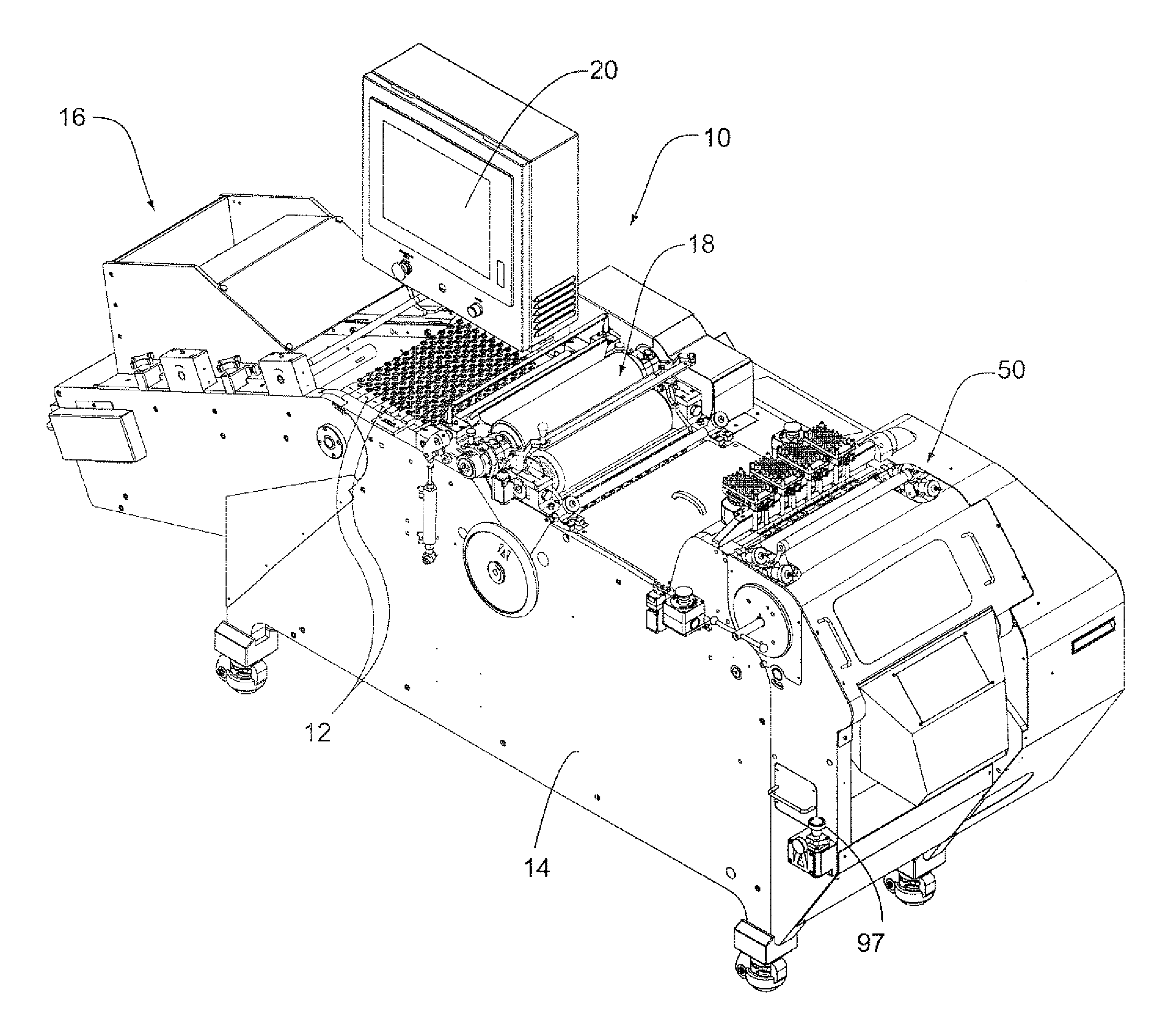
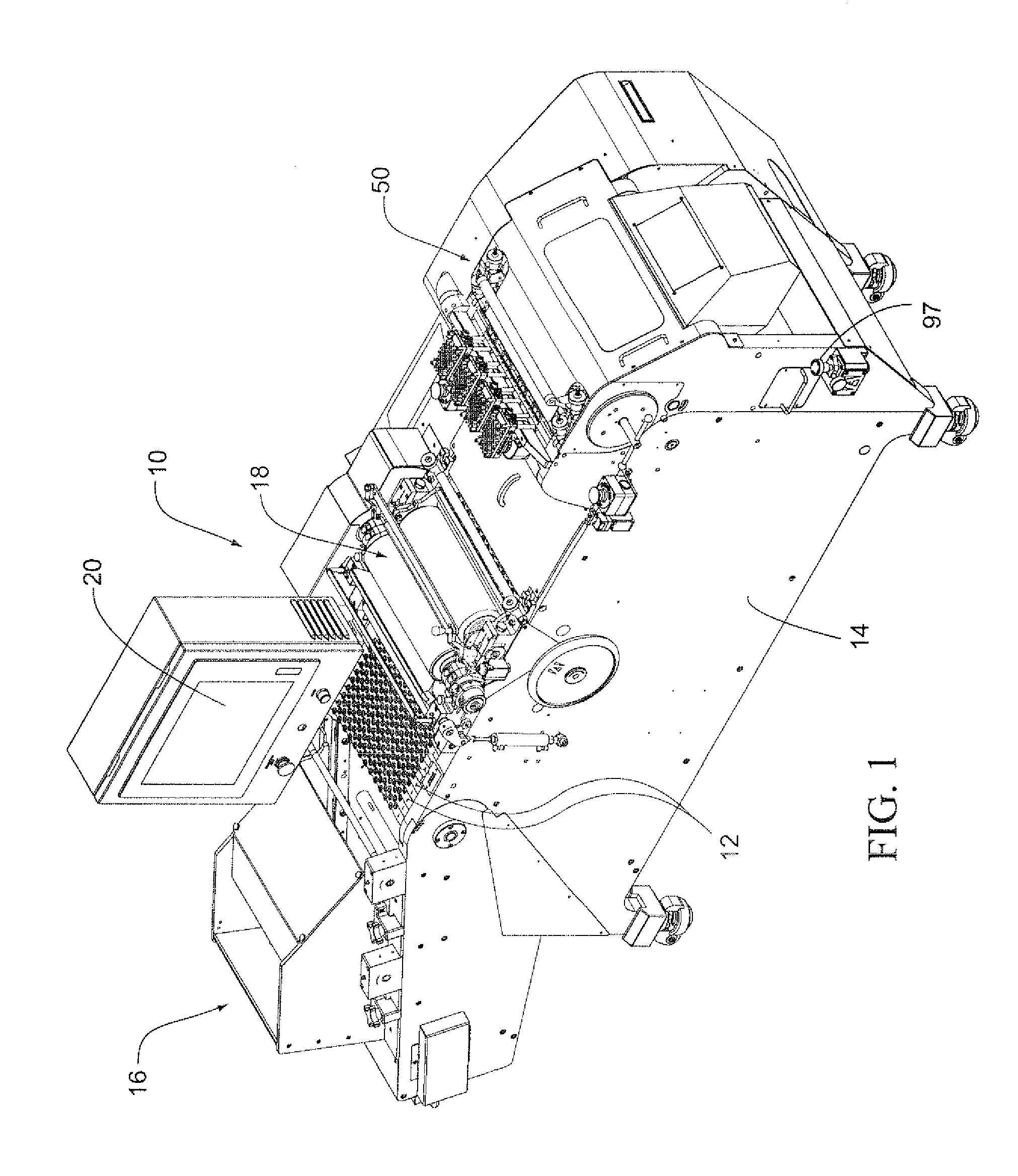
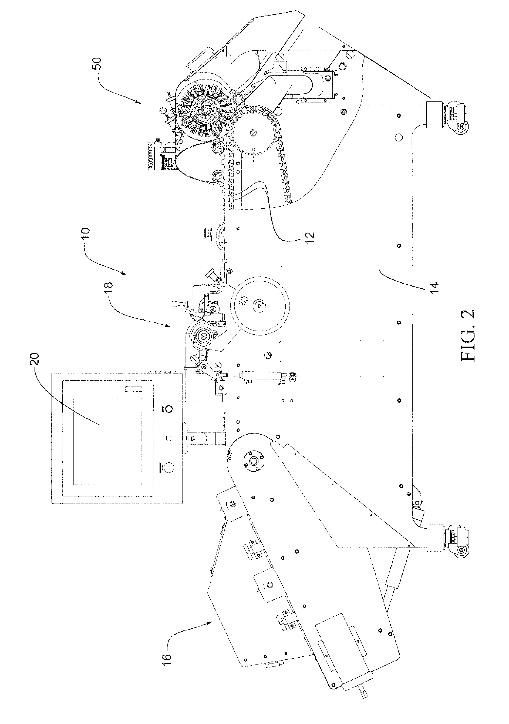
[0067]Certain forms of the invention relate to a variable ramp printer, including an offset printer with automatic print quality vision inspection and / or defective product removal. Thus, certain forms of the invention are configured to produce high-quality printed product at production rates with a reduced amount of operator interface and maintenance. Safety devices may be built into the system, e.g., to help ensure safe operation and maintenance by trained personnel.

[0068]As an overview of certain example techniques, it is noted that the variable ramp printer may operate by placing product int...


PUM

PropertyMeasurementUnit
lengthaaaaaaaaaa
lengthaaaaaaaaaa
suctionaaaaaaaaaa

Abstract

An inspection system is configured for use with a conveyer apparatus including carrier bars. Each carrier bar conveys pellet-shaped articles along a predetermined path. The inspection system includes at least one camera unit for sensing a predetermined characteristic of the pellet-shaped articles, a removal unit, and a controller. The removal unit, downstream from the at least one camera unit, removes selected pellet-shaped article(s) from the carrier bar(s) depending on whether the characteristic is sensed by the at least one camera unit. The controller is in communication with the at least one camera unit and the removal unit. The controller provides a signal to the removal unit in accordance with the sensed characteristic. The removal unit includes a rotatable ejection drum having extended vacuum nozzles along its length, equal to the number of articles conveyed in each carrier bar. Each vacuum nozzle selectively removes article(s) from the carrier bar(s) by suction.

Description

CROSS-REFERENCE TO APPLICATION[0001]This application claims the benefit of U.S. Provisional Application Nos. 61 / 485,109, filed May 11, 2011; 61 / 457,022, filed Dec. 9, 2010; and 61 / 344,150, filed Jun. 1, 2010. The entire contents of each are incorporated herein by reference.FIELD OF THE INVENTION[0002]The present invention relates to a system for inspecting and removing pellet-shaped articles (e.g., tablets) from a conveyer apparatus based on predetermined criteria.BACKGROUND OF THE INVENTION[0003]Processing of tablets, such as inspecting, marking, and / or laser drilling of tablets, is known in the art. Inspection units are typically configured to inspect and remove tablets from a conveyer mechanism that have been improperly processed in a previous processing operation. Previous processing operations may include marking the tablets with indicia, coloring the tablets, laser drilling holes in the tablets, and / or coating the tablets. These processing operations are typically completed up...

Claims


Application Information

Patent Timeline
Patent Type & Authority Applications(United States)
IPC IPC(8): B07C5/342B07C5/00B07C5/34
CPCB07C5/3422G01N21/85Y10T29/49826B07C5/34B07C5/3412G01N2021/845G01N21/9508B07C5/363B07C5/362G01N2201/02G01N2201/062G01N2201/0621G01N21/8806G01N2021/8592G01N21/8851
Inventor ACKLEY, E. MICHAELFORD, MARK
Owner ACKLEY MACHINE
Learn More