Portable radio communication device

a radio communication device and portable technology, applied in telephonic communication, substation equipment, electrical equipment, etc., can solve the problems of not easy for users to perceive or remember the purpose of the specified frequency, fm communication devices tend to generate big noise in the absence of received signals, and the audio output of the communication device is forcedly unmuted

Inactive Publication Date: 2011-12-08
JVC KENWOOD CORP A CORP OF JAPAN
View PDF7 Cites 6 Cited by
  • Summary
  • Abstract
  • Description
  • Claims
  • Application Information

AI Technical Summary

Benefits of technology

[0015]It is an object of this invention to provide a portable or handheld radio communication device which enables a user to easily perceive or remember the purpose of each specified frequency registered in a memory channel, which enables the user to simultaneously get indicated numerals of a specified frequency to be used for signal transmission and check whether or not the to-be-used specified frequency is already in use by another, and which enables the user to change a specified frequency registered in a memory channel while monitoring the specified frequency.
[0031]This invention has the following advantage. In the case where a frequency assigned to a memory channel is currently selected and used by the radio section, when the mute cancel operation section or the switch is operated, the frequency is indicated by the display and hence can be directly confirmed. Furthermore, the frequency is monitored through the radio section so that a check can be made as to whether a received signal is present in or absent from the frequency.

Problems solved by technology

In the case where only numerals representative of each specified frequency assigned to a memory channel are indicated on a display of a communication device, it is not easy for a user to perceive or remember the purpose of the specified frequency.
An FM communication device tends to generate big noise sound in the absence of a received signal.
Thus, in this case, the audio output of the communication device is forcedly unmuted even when the recovered digital data differs in contents from the reference digital data.
Furthermore, the handheld device has a severely limited number of operation switches.
Thus, to implement writing data into a memory of the device or editing data in the memory, a user is required to perform complicated operation through the use of the operation switches.
In the case where a specified frequency registered in a memory channel needs to be changed during operation of the device, a user is required to perform more complicated operation.
This causes an inconvenience to prevent the frequency used for signal transmission from being off the allowed frequency bands.

Method used


Image

  • Portable radio communication device
  • Portable radio communication device
  • Portable radio communication device

Examples


first embodiment

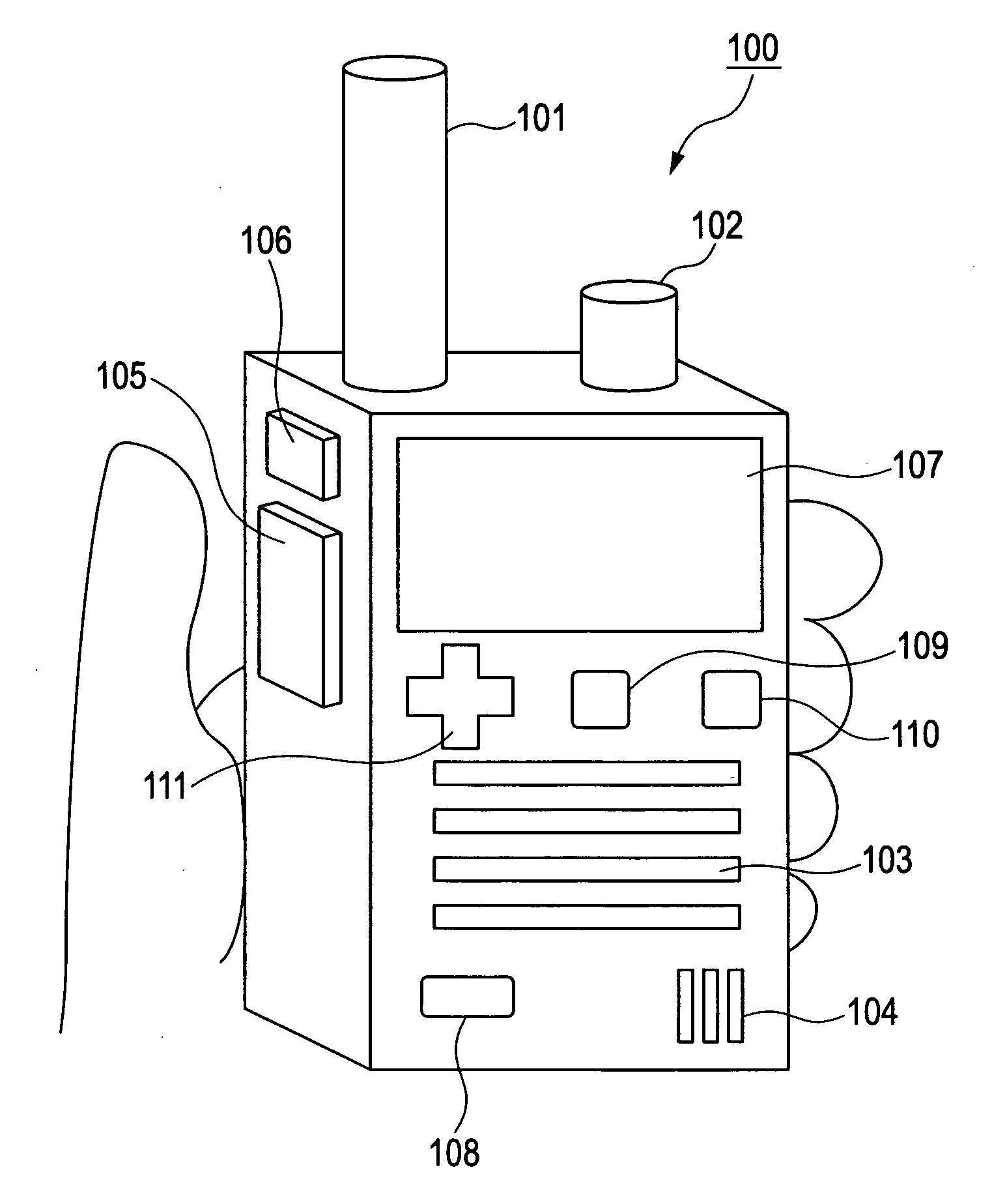
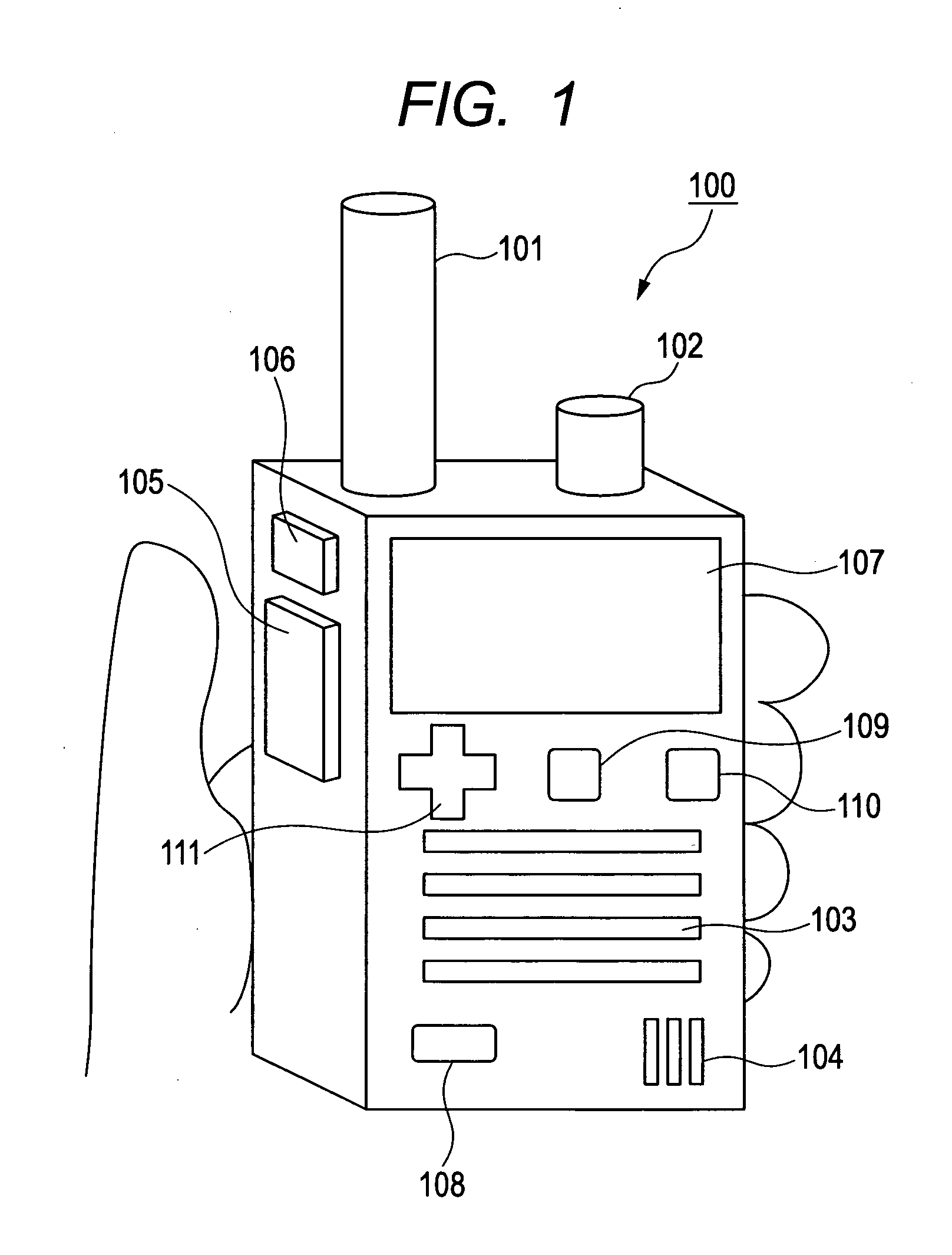
[0037]With reference to FIG. 1, a portable or handheld radio communication device 100 in a first embodiment of this invention includes a body having a top provided with an antenna 101 and a rotary encoder 102 for frequency control or frequency selection.

[0038]The body of the communication device 100 has a front provided with a loudspeaker grill 103, microphone apertures 104, a display 107, a power supply switch 108, a VFO / memory change switch 109, a memory write switch 110, and a directional pad or a cross key 111.

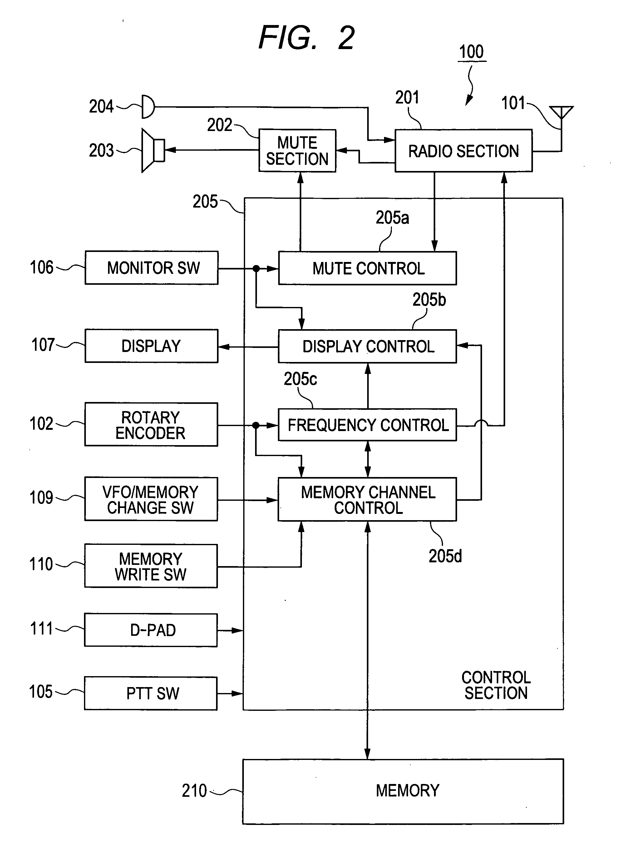
[0039]The communication device 100 can operate in either a VFO (variable frequency oscillator) mode or a memory channel mode. During the VFO mode of operation, a VFO in the communication device 100 is enabled so that the frequency to which the communication device 100 tunes is variable among frequencies spaced at predetermined intervals. In this case, varying the frequency to which the communication device 100 tunes can be implemented by actuating the rotary encoder 102. D...

second embodiment

[0102]A second embodiment of this invention is similar to the first embodiment thereof except for design changes explained below.

[0103]In the second embodiment of this invention, the steps S409 and S410 are omitted so that the step S408 is directly followed by the step S411. Therefore, regarding the memory 210, the frequency data in the stored data set about the currently-used memory channel “n” is prevented from being updated to the frequency data representative of the change-result frequency. Accordingly, the original frequency data in the stored data set about the currently-used memory channel “n” is protected. The control section 205 discards the frequency data representative of the change-result frequency when use thereof ends.

third embodiment

[0104]A third embodiment of this invention is similar to the first embodiment thereof except for design changes explained below.

[0105]In the third embodiment of this invention, the memory channels are separated into a first group and a second group. For each memory channel in the first group, the steps S409 and S410 are present so that as in the first embodiment of this invention, the frequency data in the intra-memory data set about the memory channel is updated to the frequency data representative of the change-result frequency when the frequency to which the radio section 201 tunes has been changed by the step S407.

[0106]For each memory channel in the second group, the steps S409 and S410 are omitted so that the step S408 is directly followed by the step S411. Therefore, regarding the memory 210, the frequency data in the stored data set about the memory channel is prevented from being updated to the frequency data representative of the change-result frequency as in the second em...


PUM


Abstract

A portable radio communication device includes a radio section using a frequency for at least one of signal reception and signal transmission. The frequency used by the radio section is set to a frequency assigned to a memory channel. A mute circuit mutes an audio output circuit when a mute-cancel or monitor switch is not operated, and unmutes the audio output circuit when the switch is operated. A display is controlled to indicate a name assigned to the memory channel when the switch is not operated, and to indicate the frequency assigned to the memory channel when the switch is operated.

Description

BACKGROUND OF THE INVENTION[0001]1. Field of the Invention[0002]This invention relates to a portable or handheld radio communication device which can change a frequency registered in or assigned to a memory channel while monitoring the frequency.[0003]2. Description of the Related Art[0004]Generally, a portable or handheld radio communication device is designed for transmitting and receiving signals of frequencies in a predetermined range. In most cases, the communication device does not use all frequencies in the predetermined range but uses specified frequencies selected from the predetermined range only. The specified frequencies are registered in or assigned to respective memory channels through the use of a memory in the communication device. For example, one of the specified frequencies assigned to the respective memory channels is retrieved from the memory before being used by the communication device.[0005]In the case where only numerals representative of each specified freq...

Claims


Application Information

Patent Timeline
Patent Type & Authority Applications(United States)
IPC IPC(8): H04B1/38H04B1/10H04B1/3822H04B1/40
CPCH04M1/72519H04M1/0279H04M1/724
Inventor NAMIMA, HISANOBU
Owner JVC KENWOOD CORP A CORP OF JAPAN
Why Eureka
Try Eureka