
Reclining seating unit with wall-proximity capability

a technology of wall-proximity mechanism and reclining seat, which is applied in the field of sitting units, can solve the problems of inability to position chairs, inability to manufacture wall-proximity mechanism or wheel/rail system, and high production cost of these mechanisms

Inactive Publication Date: 2011-12-15
ULTRA MEK
View PDF5 Cites 44 Cited by
  • Summary
  • Abstract
  • Description
  • Claims
  • Application Information

AI Technical Summary

Benefits of technology

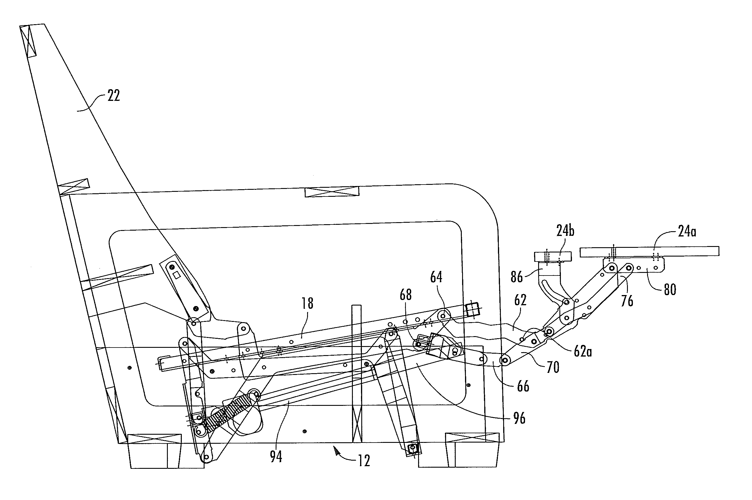
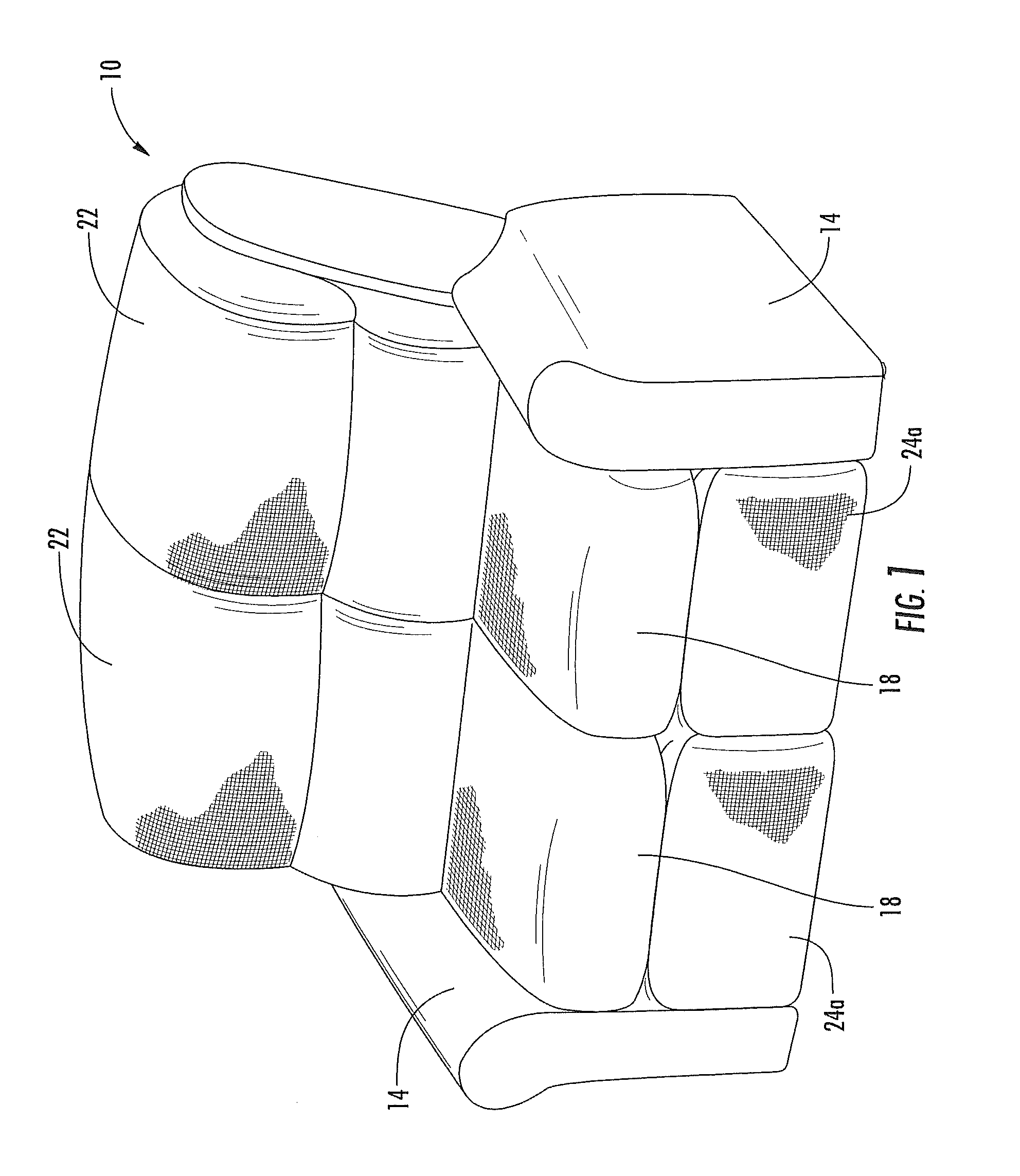
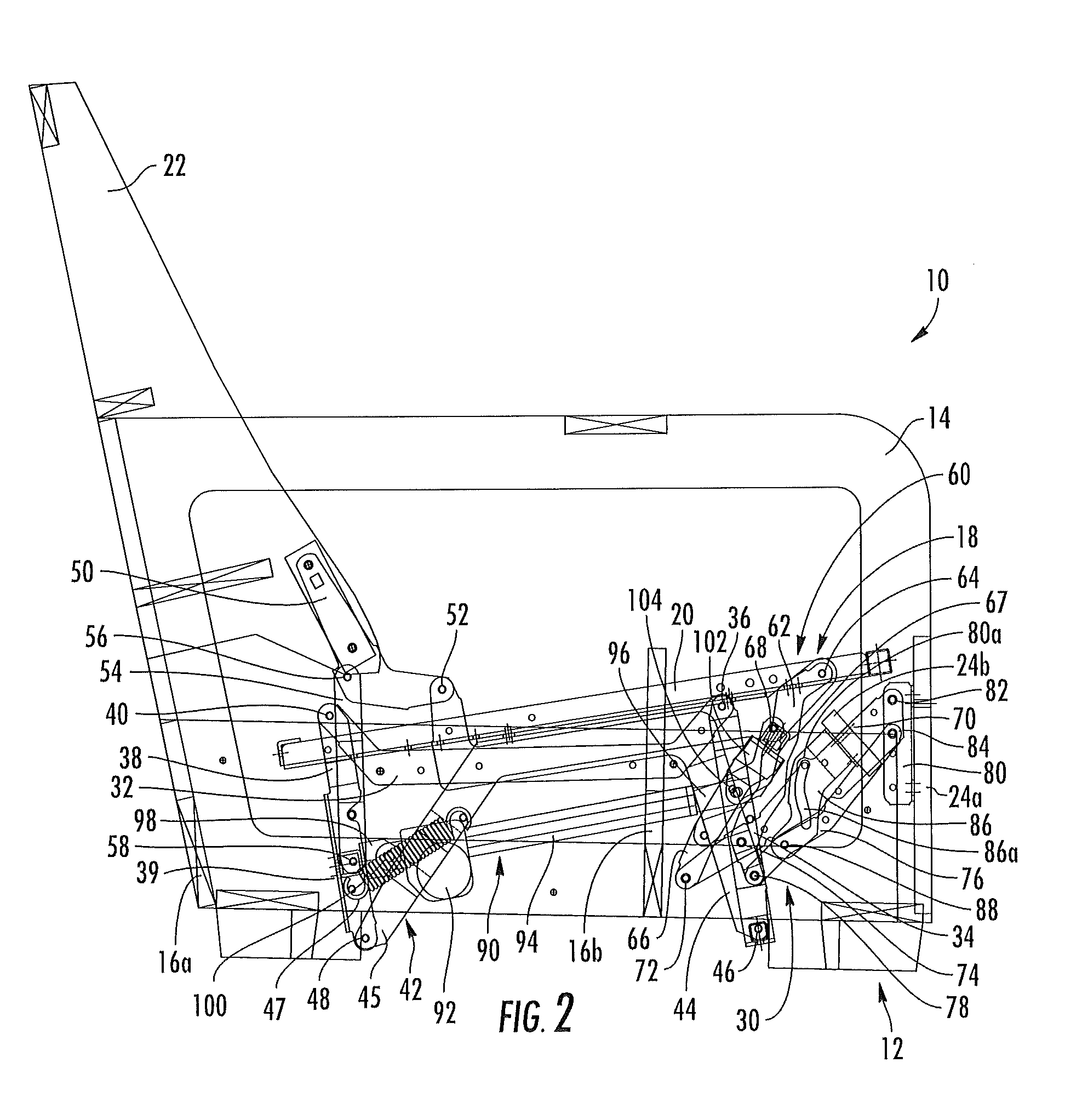
The present invention is directed to a seating unit that can be adjusted between an upright position, a TV position, and a fully reclined position. The seating unit includes a base, seat, backrest, and ottoman. The reclining mechanism is controlled by a series of pivotally interconnected links, which allow the seating unit to move between the upright and fully reclined positions. The backrest and seat are stationary relative to the base when the seating unit moves between the upright and TV positions. The seat moves upward between about 3 and 6 inches when the seating unit moves between the TV and fully reclined positions. The invention provides a seating unit that can provide wall-proximity capability and offers improved comfort and adjustability for the user.

Problems solved by technology

As a result, typically the chair cannot be positioned such that the backrest is adjacent a wall, as the reclining backrest would strike the wall and thereby be prevented from fully reclining.
One potential shortcoming of wall-proximity chairs is that the wall-proximity mechanism or wheel / rail system is typically somewhat complex, with multiple interconnected intricate parts.
As such, production of these mechanisms can be relatively expensive.

Method used


Image

  • Reclining seating unit with wall-proximity capability
  • Reclining seating unit with wall-proximity capability
  • Reclining seating unit with wall-proximity capability

Examples


Embodiment Construction

[0013]The present invention now is described more fully hereinafter with reference to the accompanying drawings, in which embodiments of the invention are shown. This invention may, however, be embodied in many different forms and should not be construed as limited to the embodiments set forth herein; rather, these embodiments are provided so that this disclosure will be thorough and complete, and will fully convey the scope of the invention to those skilled in the art.

[0014]Like numbers refer to like elements throughout. In the figures, the thickness of certain lines, layers, components, elements or features may be exaggerated for clarity. Broken lines illustrate optional features or operations unless specified otherwise.

[0015]Unless otherwise defined, all terms (including technical and scientific terms) used herein have the same meaning as commonly understood by one of ordinary skill in the art to which this invention belongs. It will be further understood that terms, such as thos...


PUM


Abstract

A seating unit includes: a base configured to rest on an underlying surface; a seat; a backrest; an ottoman; and a reclining mechanism attached to the base, seat, backrest and the ottoman. The reclining mechanism comprises a series of pivotally interconnected links configured and arranged to control the movement of the seating unit between an upright position, in which the seat is generally horizontally disposed and positioned above the base, the backrest defines a first backrest angle relative to horizontal and is positioned above a rear portion of the base, and the ottoman is positioned below the seat and above a forward portion of the base, a TV position, in which the ottoman is generally horizontally disposed and positioned forwardly of the base and the seat, and a fully reclined position, in which the backrest defines a second angle relative to horizontal that is less than the first angle. The backrest and seat are substantially stationary relative to the base as the seating unit moves between the upright and fully reclined positions. An uppermost portion of the backrest moves no more than 4 inches rearward relative to the base as the seating unit moves from the TV position to the fully reclined position. In this configuration, the seating unit can provide wall-proximity capability.

Description

FIELD OF THE INVENTION[0001]This invention relates generally to seating units, and relates more particularly to reclining seating units with gliding capability.BACKGROUND OF THE INVENTION[0002]Recliner chairs and other reclining seating units have proven to be popular with consumers. These seating units typically move from an upright position, in which the backrest is generally upright, to one or more reclined positions, in which the backrest pivots to be less upright. The movement of the seating unit between the upright and reclined positions is typically controlled by a pair of matching reclining mechanisms that are attached to the seat, backrest and base of the chair.[0003]One particularly popular reclining chair is the so-called “wall-proximity” chair. In a conventional reclining chair, as the backrest moves to the reclined position, the upper end of the backrest moves rearwardly relative to the base of the chair. As a result, typically the chair cannot be positioned such that t...

Claims


Application Information

Patent Timeline
Patent Type & Authority Applications(United States)
IPC IPC(8): A47C1/035
CPCA47C1/034
Inventor MURPHY, MARCUS L.HOFFMAN, D. STEPHEN
Owner ULTRA MEK
Learn More