Variable rate RC calibration circuit with filter cut-off frequency programmability

Inactive Publication Date: 2005-06-02
PROCOMM
View PDF3 Cites 35 Cited by
  • Summary
  • Abstract
  • Description
  • Claims
  • Application Information

AI Technical Summary

Benefits of technology

[0013] Moreover, by tuning the resistance of the programmable resistors with the ratio of the changed cut-off frequency to the default cut-off frequency, the cal

Problems solved by technology

Nevertheless, one severe issue in FIG. 2 is that if there exists a DC offset on the opamp, the Vo acts like the ones shown in FIG. 4.
It therefore changes the counter enabled duration (to be η′ or η″ instead of η) and results in wrong calibration codes.
In addition, the input DC offset voltage on the followed comparator also causes the deviation of η and results in another failure reason for this calibration circuit.
Unfortunately, the DC offset on the opamp and comparator is inherent and unpredictable in the monolithic process.
There are some ways to store th

Method used


Image

  • Variable rate RC calibration circuit with filter cut-off frequency programmability
  • Variable rate RC calibration circuit with filter cut-off frequency programmability
  • Variable rate RC calibration circuit with filter cut-off frequency programmability

Examples


Example

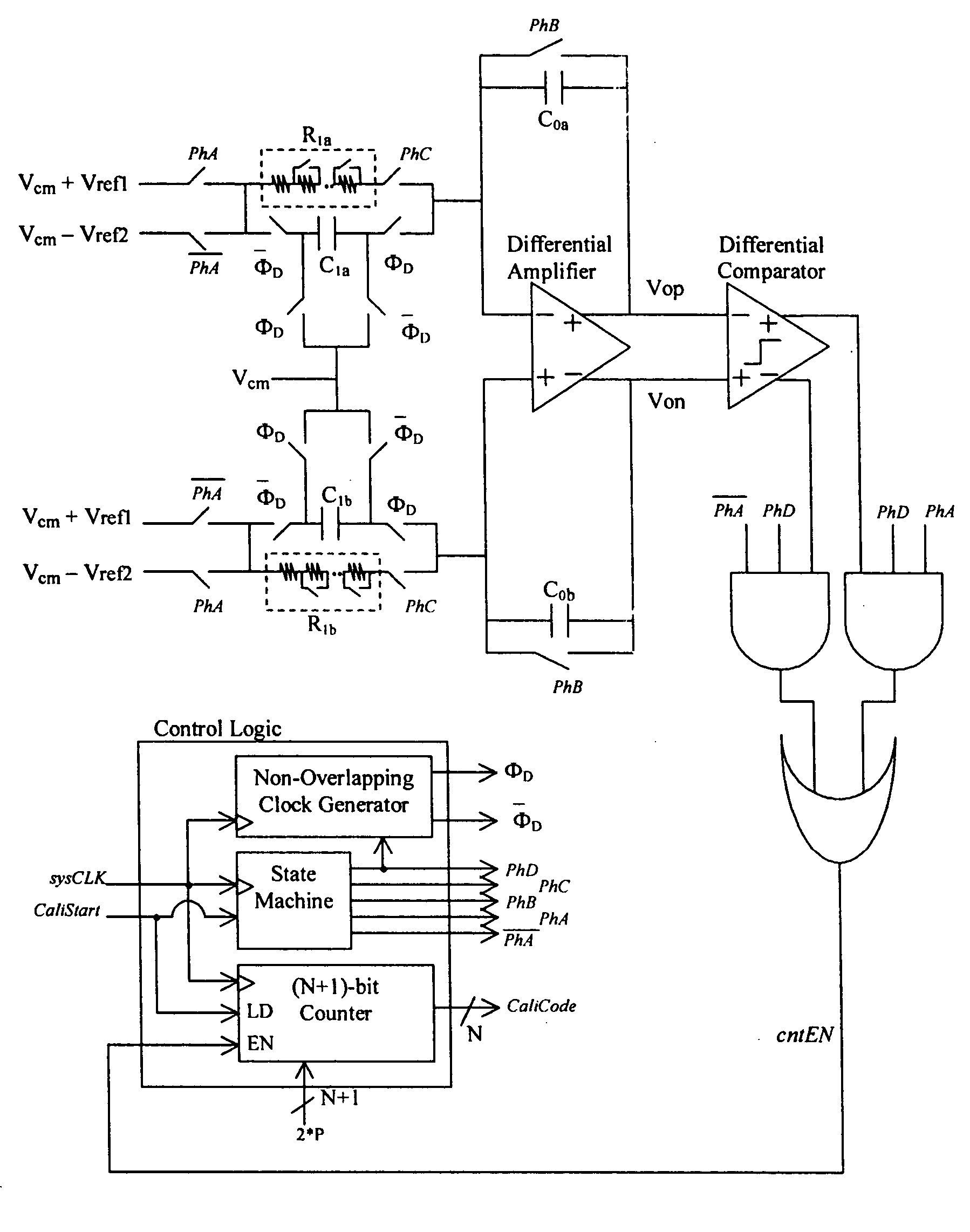
[0022]FIG. 5 is the schematic diagram that shows a self-tuned RC calibration circuitry in accordance with the present invention. FIG. 6 is the timing diagram demonstrating the operation in FIG. 5. Note that both feedback capacitors C0a and C0b have the same capacitance of C0, both switched capacitor resistors C1a and C1b have the same capacitance of C1, and both programmable resistors R1a and R1b have the same resistance of R1. During the 1st calibration cycle, the difference of the differential amplifier outputs, (Vop−Von), changes slopes as a first dual-slope ramp signal with gradients of [∂(Vop−Von) / ∂t]−=−(Vref1+Vref2) / (R1*C0*τ) and [∂(Vop−Von) / ∂t]+=(Vref1+Vref2)*C1 / (C0*Tclk), where τ is the ratio of nominal to ideal on-chip RC time constant and Tclk is the period of a precise reference clock. Timing arrangement is created such that the circuit is auto-zeroed (shortening individual two ends of C0a and C0b) for certain amount of Tclk cycles to settle all circuitry. Thereafter, (Vo...


PUM


Abstract

Two reference signals are applied to an RC calibration circuit, which utilizes programmable resistors and switched capacitor resistors in parallel at the inputs of a differential amplifier with feedback capacitors, for the first cycle and then the two reference signals are swapped for the successive cycle. The circuit inherent DC offset is cancelled by these two successive cycles. The time duration when the difference of the differential amplifier outputs in the calibration circuit starts to reverse ramping direction and the time when the difference crosses zero is counted in terms of reference clock cycles by a binary counter. The binary count is used to select the capacitance of the capacitor arrays in an RC filter for time constant calibration. This calibration circuit provides the flexibility for various reference clock rates by adjusting the programmable resistors. By tuning the same programmable resistors, this calibration circuit in addition provides the capability to changing the cut-off frequency of an RC filter circuit to another predetermined value.

Description

BACKGROUND OF THE INVENTION [0001] 1. Field of Invention [0002] The present invention relates to resistor and capacitor monolithic process calibration and, more particularly, to an RC calibration circuit with filter cut-off frequency programmability for filters that include resistors and capacitors in their structures. [0003] 2. Description of Related Art [0004] The on chip resistors (R) and capacitors (C) can vary over a huge range even in most updated monolithic process. The variation of the RC directly causes the deviation of the filter cut-off frequency. One way of compensating the filter cut-off frequency deviation is through the use of a set of tunable capacitor array controlled by an RC calibration circuit. The RC calibration circuit simply adjusts the capacitance in the filter capacitor array to bring the cut-off frequency back to the desired value. [0005]FIG. 1 shows a exemplary application for the RC calibration circuit to compensate the cut-off frequency deviation of a fi...

Claims


Application Information

Patent Timeline
IPC IPC(8): H03F1/34H03F3/45H03H11/12H03H19/00H04B1/30
CPCH03F1/34H03F3/45475H03F3/45968H03F3/45977H03F2200/78H04B1/30H03F2203/45424H03F2203/45514H03H11/1291H03H19/004H03F2203/45212
Inventor PAI, HUNG-CHUANDAI, LIANGWANG, KEVIN HSI-HWAIHUANG, JIE
Owner PROCOMM
Why Eureka
Try Eureka