Retractable wide-span vehicle barrier system

a wide-span, vehicle-mounted technology, applied in roadway safety arrangements, roads, construction, etc., can solve the problems of limited barrier systems, system not directly applicable to vehicle-mounted barriers, and limited range of barriers, so as to achieve convenient deployment

Active Publication Date: 2006-08-01
BARRIER1 SYST LLC
View PDF29 Cites 32 Cited by
  • Summary
  • Abstract
  • Description
  • Claims
  • Application Information

AI Technical Summary

Benefits of technology

[0007]The invention addresses the above needs and achieves other advantages by providing a barrier system that is modular and easily deployed. Preferably the barrier system is capable of stopping a 15,000 lb vehicle at impact speed exceeding 50 mph, which can free span up to 250 feet without need for intermediate fixed supports. An objective of this invention is to provide capability to raise or lower barrier net system in less than 60 seconds, to allow a vehicle to drive over a lowered net without causing damage to the system, and to completely disconnect and remove the barrier system in less than 10 minutes so that vehicle access to the secured area is restored. Another objective of this invention is to allow for steel sleeves embedded in concrete, so that vertical steel supports can be slid in or slid out. Another objective of this invention is to eliminate requirement for an external power or fuel source making this barrier system self-sufficient and able to operate in remote locations. Another objective of this vehicle barrier system is to provide wireless control to raise or lower barrier net from a remote location, such as with a satellite phone or the like. Another objective of this invention is to make system components modular, meet military shipping requirements regarding size and weight, with ability to package and ship barrier system anywhere. Another objective of this invention is to provide end supports, energy absorption systems, components, and connections that are reusable, without requiring extensive repair after a major impact event. Another objective of this invention is to be able to disconnect system components without causing destruction. Another objective of this invention is to provide alarm capability to signal a vehicle impact event. Another objective of this invention is to provide components that are “all weather” use. Another objective of this barrier system is to have visibility through the barrier, allowing one to see an oncoming vehicle. Another objective of this vehicle barrier system is to not cause loss of life upon major vehicle impact event, allowing for interrogation of driver. Another objective of this invention is to prevent total vehicle destruction upon impact, allowing preservation of evidence. As such, the barrier system of the present invention provides protection against possible terrorist activities, particularly truck-loaded bombs in remote locations.

Problems solved by technology

Such systems are not directly applicable to vehicle barrier systems because the net system, energy absorption units, and end supports of vehicle barrier systems are designed to completely stop vehicle over a short distance regardless of the amount of damage caused to the vehicle.
These barrier systems are limited by the length of area that can be secured without adding fixed supports that penetrate the subsurface, and this limitation is typically 15 to 60 feet.
In addition, these barrier systems require an electrical power supply, require backup power systems, and use hydraulics or pistons, resulting in maintenance, repairs, and downtime of the barrier.
Many of these systems are not an “all weather” use.
These barrier systems are either semi-fixed in-place and are not easily removed, or permanently fixed in-place and, therefore, permanently block off vehicle access to the secured area.
Onsite installation of prior art systems can take several weeks.
System components are neither modular nor disconnected easily.
Barriers made of steel and concrete create additional projectiles upon an impact event, and require significant repair work in the aftermath to restore a barrier to operational status.

Method used


Image

  • Retractable wide-span vehicle barrier system
  • Retractable wide-span vehicle barrier system
  • Retractable wide-span vehicle barrier system

Examples


Embodiment Construction

[0018]The present invention now will be described more fully hereinafter with reference to the accompanying drawings, in which some, but not all embodiments of the invention are shown. Indeed, the invention may be embodied in many different forms and should not be construed as limited to the embodiments set forth herein; rather, these embodiments are provided so that this disclosure will satisfy applicable legal requirements.

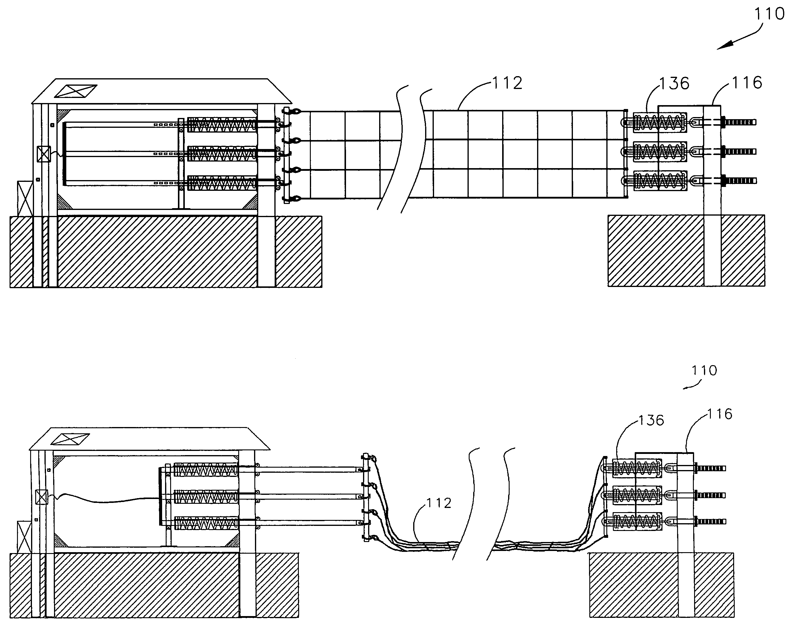
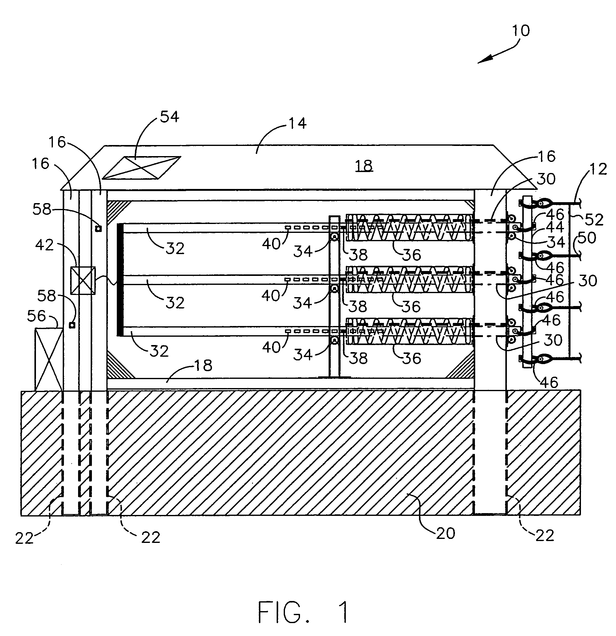
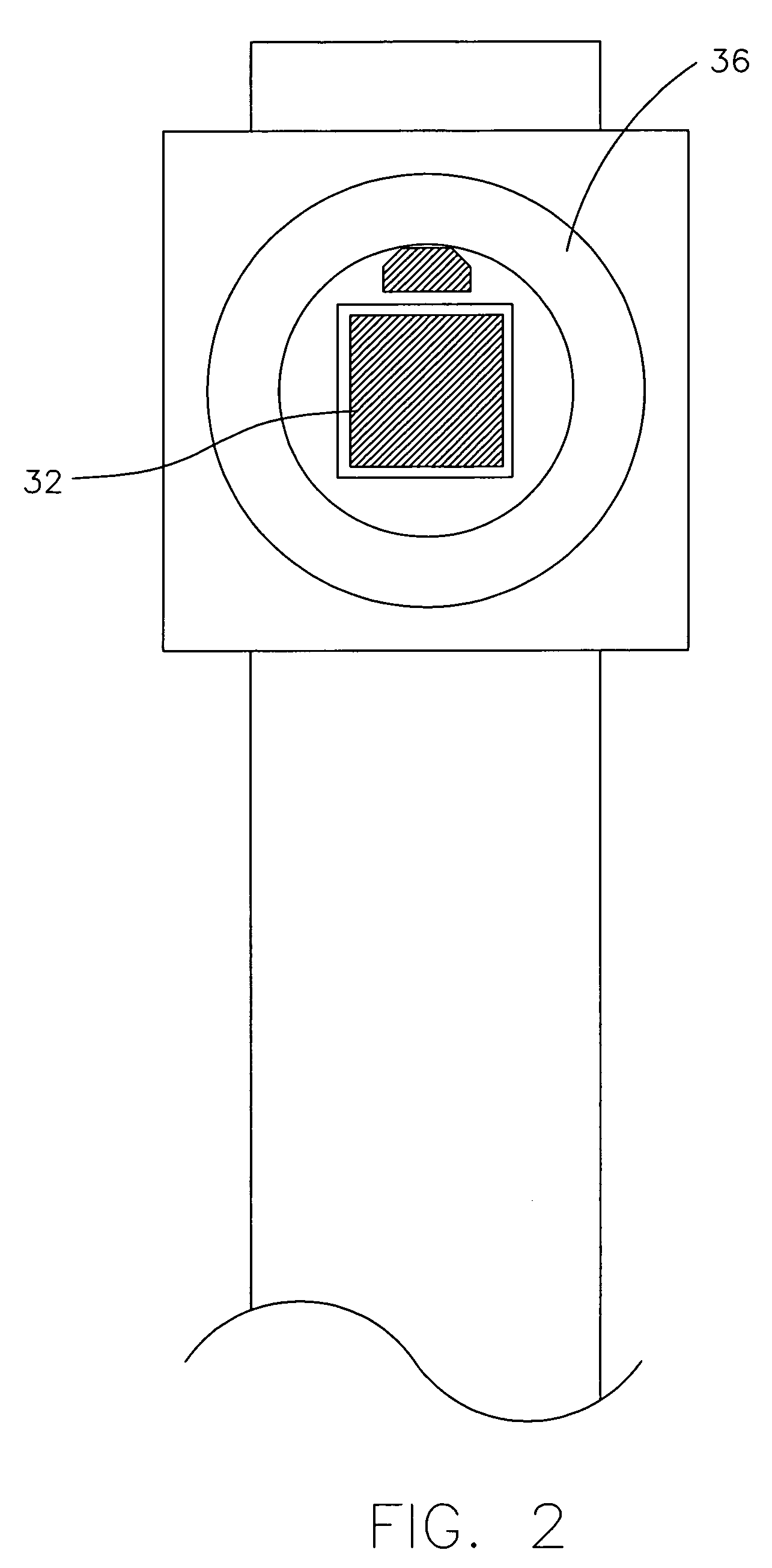
[0019]With reference to FIGS. 1–6, a barrier system 10 in accordance with one embodiment of the present invention is illustrated. The barrier system 10 includes a net system 12 that is supported on each of two ends by an end support 14. Each end support 14 preferably includes three (3) vertical steel tubes 16 arranged in a triangular pattern, with the 8″×12″ larger steel tube in front and the two (2) smaller 6″×6″ steel tubes at the rear. Each of the three (3) vertical steel tubes 16 are connected together for structural support using a 4″×4″ horizontal steel me...


PUM


Abstract

A vehicle barrier system that stops unwanted vehicle intrusion, controls vehicle access, and protects assets and critical infrastructure. The vehicle barrier system, which can span up to 250 feet without requiring fixed intermediate supports, will stop a 15,000 lb vehicle traveling at impact speed of 50 mph. The barrier net is attached to vertical steel end supports anchored in concrete, and include energy absorbers, pivoting connections, and force equalization bars. The barrier net can remain in the “up” or “down” position, and can be raised or lowered using a winch powered by common 12 volt battery with solar power recharge. The barrier net and system components are modular, and can be easily installed or removed.

Description

CROSS REFERENCE TO RELATED APPLICATION[0001]The present application claims priority pursuant to 35 U.S.C. 119(e) to U.S. Provisional Application Ser. No. 60 / 639,935, filed Dec. 29, 2004.BACKGROUND OF THE INVENTION[0002]1. Field of the Invention[0003]The present invention is related to vehicle barrier systems, and more particularly to net-based vehicle barrier systems that span a long distance that can be readily raised or lowered and that can be easily deployed.[0004]2. Description of Related Art[0005]Originally, net-based barrier systems with energy absorption devices at end supports were associated with aircraft arresting devices. These systems are designed so that the aircraft arresting net system is let out more than 100 feet upon impact and the aircraft slowly decelerates to a stop over a long distance, to minimize damage to the aircraft. Such systems are not directly applicable to vehicle barrier systems because the net system, energy absorption units, and end supports of vehi...

Claims


Application Information

Patent Timeline
Patent Type & Authority Patents(United States)
IPC IPC(8): E01F15/00
CPCE01F13/12
Inventor LAMORE, MICHAEL J.
Owner BARRIER1 SYST LLC
Why Eureka
Try Eureka