Tidal/wave flow electrical power generation system

a technology of electrical power generation and tide flow, which is applied in the direction of electric generator control, liquid fuel engines, machines/engines, etc., can solve the problems of untapped source of electrical power generation, untapped source of energy for electrical power generation, and high cos

Inactive Publication Date: 2006-10-03
CORCORAN III JAMES JOHN
View PDF7 Cites 35 Cited by
  • Summary
  • Abstract
  • Description
  • Claims
  • Application Information

AI Technical Summary

Benefits of technology

[0008]A further advantage of this invention is to provide the capability to change the generation characteristics with the flow of the water through the use of variable vane technology and a flow, current and pitch computer controllers. The invention can be used where the flow is bi-directional without physically moving the unit. The ability to change the pitch of the vanes when the flow direction changes without losing generator output through the use of both a solid state voltage device and a mechanical fly wheel assembly on the drive shaft.
[0010]A significant additional advantage is to provide a easily installed generation assembly for use by regional power companies to supplement the local grid requirements for power during all seasons and without concerns other than routine maintenance of the power generation assembly.

Problems solved by technology

This is extremely costly and limited to topographic areas where dams are adequately situated.
Up until today, technology has not been available to provide a solid state generation capability or a variable pitch capability for turbine blades.
With the advent of this capability, an application to use the shoreline tidal / wave action and the tidal action of our major rivers and estuaries in this country result in an untapped source of energy for electrical power generation.

Method used


Image

  • Tidal/wave flow electrical power generation system
  • Tidal/wave flow electrical power generation system
  • Tidal/wave flow electrical power generation system

Examples


Embodiment Construction

[0017]A detailed description of the preferred embodiment is provided herein. It is to be understood, however, that the present invention may be embodied in various forms. Therefore, specific details disclosed herein are not to be interpreted as limiting, but rather as a basis for the claims and as a representative basis for teaching one skilled in the art how to employ the present invention in an appropriately detailed system, structure or manner.

DETAILED DESCRIPTION OF THE INVENTION

[0018]The present invention provides a system, a method and a process for tidal / wave flow electrical power generation.

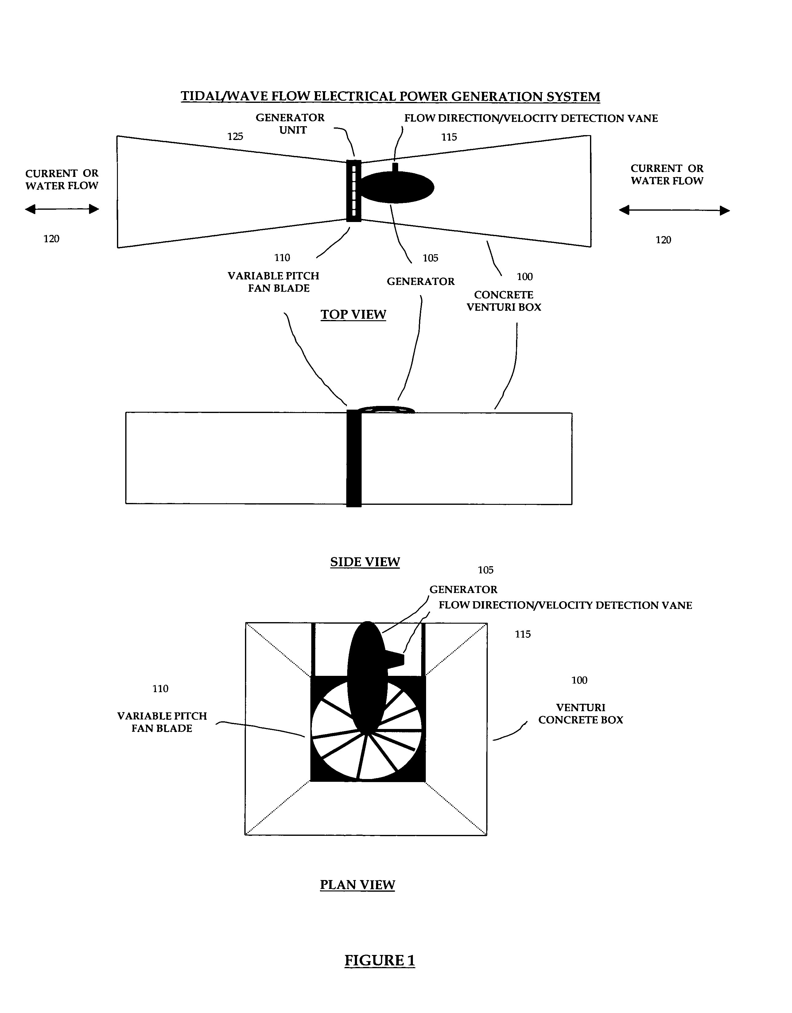
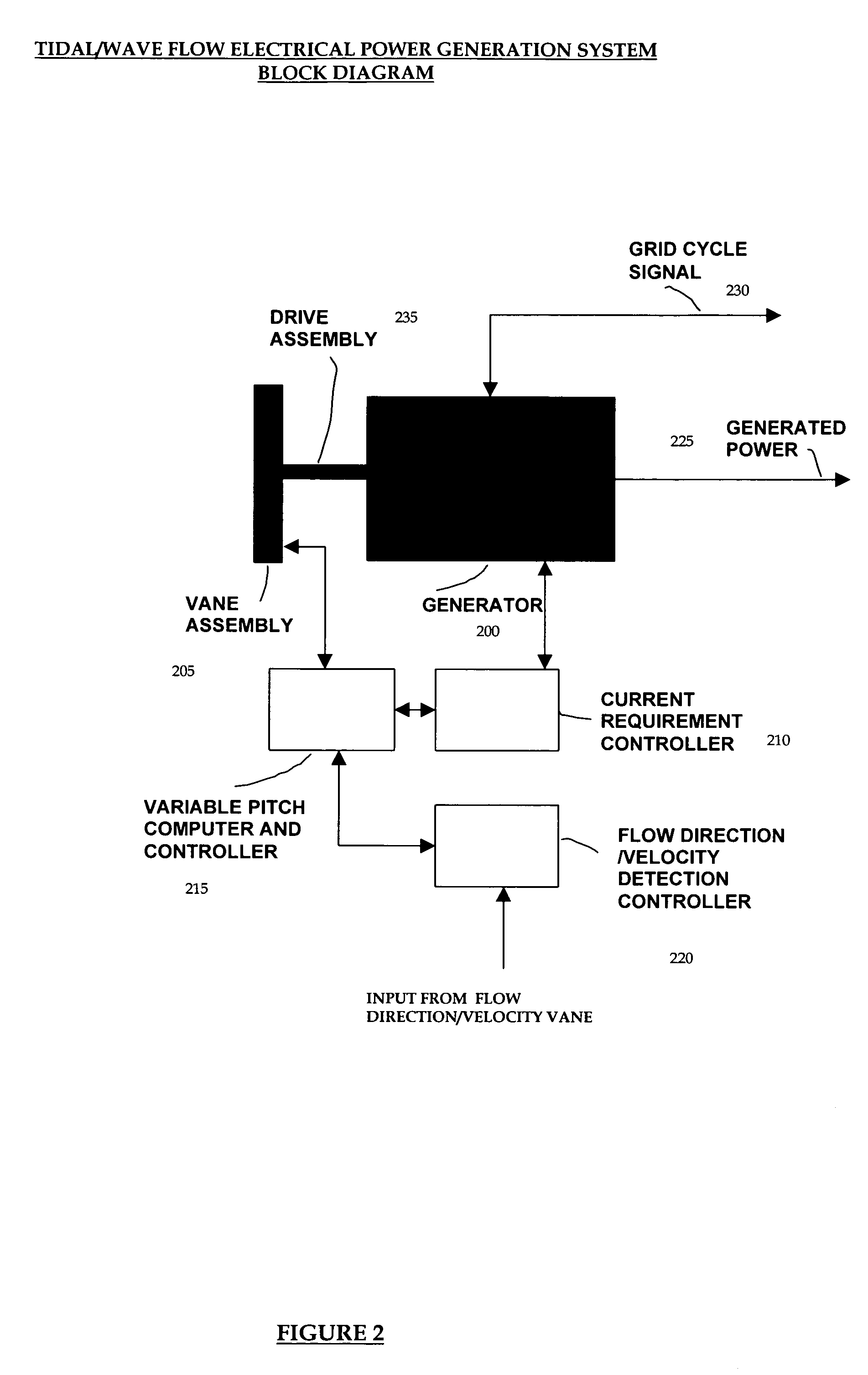
[0019]As illustrated in FIG. 1, the system generally includes a field replaceable generator unit 125, comprised of a variable pitch fan blade and vane motor control unit 110, a flow direction and velocity detection vane unit 115, a generator 105, all of which are located in the venturi concrete box unit 100. The water or current flows in and out of the venturi box at both ends of the conc...


PUM


Abstract

An integrated system for tidal / wave flow electrical power generation. This bi-directional system utilizes the wave flow on the shores and the flow of various rivers and estuaries to generate electrical power through a venturi box which has mounted in it and comprises of the following components: a vane assembly with variable pitch vanes made from high impact blade material; a drive shaft assembly that connects the vane drive unit with the generator; a flow detection vane that determines velocity and direction thereby providing input to the flow detection controller and variable pitch computer and controller; a solid state voltage regulator; a mechanical fly wheel assist for the drive assembly during transition between flow direction; a grid cycle input device to match the power being generated with the grid. This system is capable of being coupled together both physically and electrically. The generator unit assembly is a field replaceable unit to ease installation and maintenance. The venturi box design mitigates slit and sand build-up. The vane radial design limits the damage by flotsam and provides a means of reducing fish damage as well.

Description

BACKGROUND OF THE INVENTION[0001]This invention relates generally to the field of electrical power generation specifically to a system that generates power from tidal or wave motion. The virtually perpetual motion of the ocean waves and the tidal flows of rivers especially those classified as estuaries provide an endless source of energy that can be converted into electrical power.[0002]The ability to cut back on dependence on oil and fossil fuel for power generation has long been a goal of the United States government and other global governments. Previously utilities or energy companies have utilized dams to create a water source to be run through generators for electrical power generation. This is extremely costly and limited to topographic areas where dams are adequately situated. Up until today, technology has not been available to provide a solid state generation capability or a variable pitch capability for turbine blades. With the advent of this capability, an application to...

Claims


Application Information

Patent Timeline
Patent Type & Authority Patents(United States)
IPC IPC(8): F03B13/00
CPCF03B13/10F03B13/105F03B13/12F03B15/06F05B2240/97F05B2260/70F05B2260/74Y02E10/22Y02E10/20
Inventor CORCORAN, III, JAMES JOHN
Owner CORCORAN III JAMES JOHN
Why Eureka
Try Eureka