Method and system of sparse code based object classification with sensor fusion

a sensor fusion and object classification technology, applied in the field of methods and systems of sparse code based object classification with sensor fusion, can solve the problems of imposing a huge burden on the system, not teaching the use of orientation selective filters for object classification, and the amount of patterns and processes

Active Publication Date: 2009-12-31
TOYOTA MOTOR CO LTD
View PDF22 Cites 36 Cited by
  • Summary
  • Abstract
  • Description
  • Claims
  • Application Information

AI Technical Summary

Benefits of technology

[0008]A system and method for object classification based upon the fusion of a radar system and a natural imaging device using sparse code representation is provided. Specifically, a radar system is paired with a camera. The radar system provides a means of detecting the presence of an object within a predetermined path of a vehicle. Objects identified within this predetermined path are then fused with the image gathered by the camera and the detected image is provided to the user in separate windows referred to hereafter as “attention windows.” These attention windows are the natural camera image of the environment surrounding the radar return. The attention window is then transformed into a sparse code representation of the object. The sparse code representation is then compared with known sparse code representation of various objects. Each known sparse code representation is given a predetermined variance and subsequent sparse code representations falling within said variance will be classified as such. For instance, a known sparse code representation having a value of Y will be given a variance of Y+ / −V, and subsequent sparse code representations of an image of an object falling within Y+ / −V, will be classified as the object with Y. The system and method also includes an associative learning algorithm wherein classified sparse code representations are stored and used to help classifying subsequent sparse code representation, thus providing the system with the capabilities of associative learning.

Problems solved by technology

However, Malhotra does not teach the use of orientation selective filters for object classification.
Again, like Shunji et al. this system requires the data to be processed through an elaborate and complicated algorithm and thus requires a processor with that ability to process a tremendous amount of data in a relatively short period of time in order to provide the user with usable data.
However, Breed et al. is dependent upon the trained pattern recognition technique whereby the amount of patterns and processes may place a huge burden on the system.

Method used


Image

  • Method and system of sparse code based object classification with sensor fusion
  • Method and system of sparse code based object classification with sensor fusion
  • Method and system of sparse code based object classification with sensor fusion

Examples


Embodiment Construction

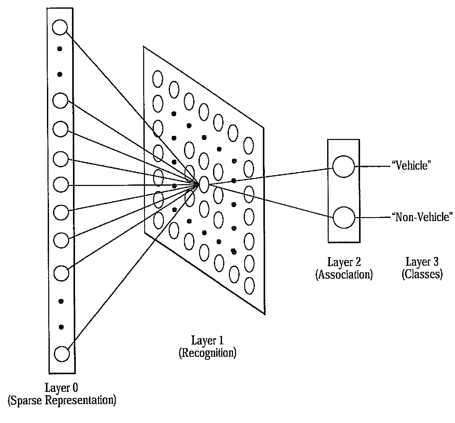
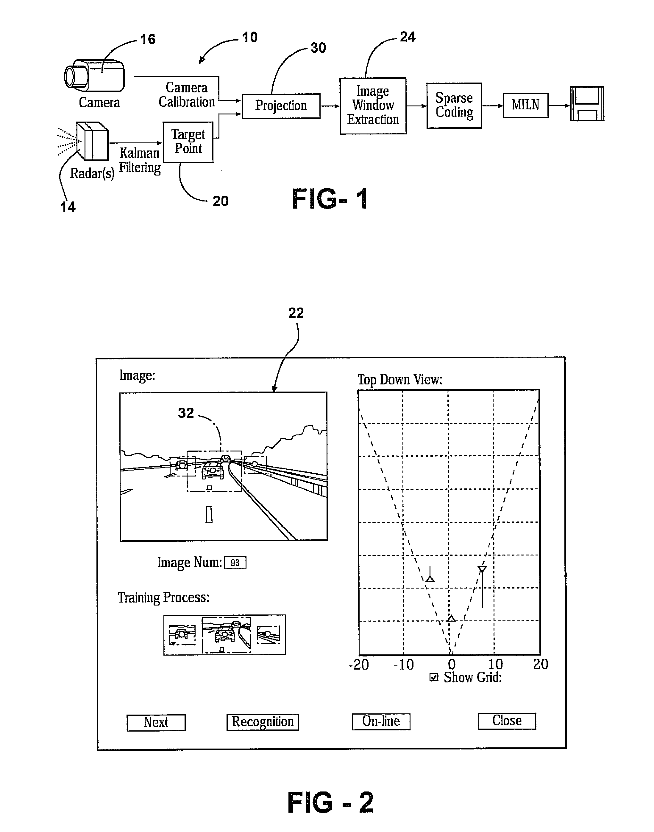
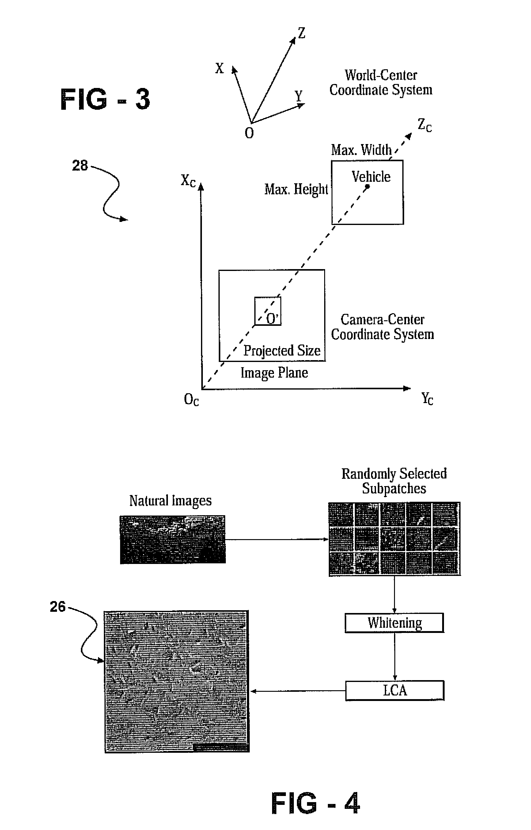
[0018]With reference to FIG. 1, a system 10 and method 12 for object classification based upon the fusion of a radar system 14 and a natural imaging device 16 using sparse code representation 18 is provided. Specifically, the system 10 fuses radar return 20 with associated camera imaging 22, and the fused data 24 is then transformed into a sparse code representation 18 and classified. The camera image of the radar return 20 is isolated, extracted and filtered with the help of orientation-selective filters 26. Processing of local receptive fields embedded onto the extracted image by orientation-selective filters 26 results in a sparse code for the image. The sparse code representation 18 of the object on the image is compared to known sparse code representations 18 of a particular object class. The processing and comparison of any subsequent sparse code representation 18 of images is done in an associative learning framework.

[0019]Thus, the video image of the object detected by the r...


PUM


Abstract

A system and method for object classification based upon the fusion of a radar system and a natural imaging device using sparse code representation. The radar system provides a means of detecting the presence of an object within a predetermined path of a vehicle. Detected objects are then fused with the image gathered by the camera and then isolated in an attention window. The attention window is then transformed into a sparse code representation of the object. The sparse code representation is then compared with known sparse code representation of various objects. Each known sparse code representation is given a predetermined variance and subsequent sparse code represented objects falling within said variance will be classified as such. The system and method also includes an associative learning algorithm wherein classified sparse code representations are stored and used to help classifying subsequent sparse code representation.

Description

BACKGROUND OF THE INVENTION[0001]1. Field of the Invention[0002]A system and method for object classification based upon the fusion of a radar system and a natural imaging device, and a sparse code representation of an identified object.[0003]2. Description of the Prior Art[0004]Sensor fusion object classification systems are known and well documented. Such systems will gather information from an active and passive sensor and associate the two data to provide the user with information relating to the data, such as whether the object is a vehicle or a non-vehicle. Such an association is commonly referred to as fusion and is referred to as such herein. In operation, fusion relates to return of a natural image captured by the passive sensor with respect to the detection of an object by the active sensor. Specifically, an active sensor such as a radar system will be paired to a passive sensor such as a video camera, and the objects detected by the radar will be mapped to the video image...

Claims


Application Information

Patent Timeline
Patent Type & Authority Applications(United States)
IPC IPC(8): H04N7/18
CPCG01S7/412G06K9/6249G06K9/00805G01S13/867G06K9/6293G06V20/58G06V10/811G06V10/7715G06F18/256G06F18/2136
Inventor JI, ZHENGPINGPROKHOROV, DANIL V.
Owner TOYOTA MOTOR CO LTD
Why Eureka
Try Eureka