Image processing apparatus, image processing method, and computer program

a technology of image data and processing apparatus, applied in the field of image processing apparatus and image processing method, and a computer program, can solve the problems of increasing the noise level, especially impairing the image quality, and the sensitivity of a ccd or cmos sensor, and achieve the effect of removing the low-frequency noise contained in image data

Inactive Publication Date: 2011-12-22
CANON KK
View PDF10 Cites 6 Cited by
  • Summary
  • Abstract
  • Description
  • Claims
  • Application Information

AI Technical Summary

Benefits of technology

[0021]The present invention has been proposed to solve the conventional problems, and has as its object to provide an image processing apparatus and image processing method, and a computer program, which can visually remove low-frequency noise contained in image data.

Problems solved by technology

As an example of the latter (noise superposed during a digital signal process), noise components are amplified simultaneously with signal components when a specific density, color, and the like are emphasized in various correction processes such as gamma correction, gain correction for improving the sensitivity, and the like, thus increasing the noise level.
In addition to various kinds of noise mentioned above, a cause that especially impairs the image quality is noise (to be referred to as “low-frequency noise” hereinafter) which is generated in a low-frequency range and is conspicuously observed in an image sensed by a digital camera or the like.
This low-frequency noise often results from the sensitivity of a CCD or CMOS sensor as a solid-state image sensing element.
Hence, in a digital camera which has a large number of pixels within a small area, the amount of light per unit pixel consequently decreases, and the sensitivity lowers, thus producing low-frequency noise.
Some digital cameras often produce false colors.
That is, since block distortion is noise that generates block-like steps different from signal components on a portion which is originally a flat portion, the steps can become hardly visible by moderating the gradients of the steps.
The aforementioned two noise removal methods can effectively work locally, but have adverse effects (blur of an edge portion and the like).
However, none of these conventional methods can exhibit a perfect noise removal effect of the aforementioned low-frequency noise.
Hence, these methods are not effective for low-frequency noise, and the low-frequency noise remains unremoved.
However, the low-frequency noise to be removed is connectivity noise, i.e., pixel values which have less changes successively appear across a broad range from several to ten-odd pixels, and the aforementioned technique that reduces block distortion cannot be directly applied.
Hence, especially in a color image, when random numbers are added to respective color components obtained by color separation, a new color which is not present in surrounding pixels is generated, and deterioration of image quality such as generation of false colors or the like occurs.
However, since this moire removal method aims at disturbing a specific period corresponding to a peak, it is not completely effective for low-frequency noise, which is generated in a broad low-frequency range.
As described above, none of the aforementioned prior arts can effectively remove low-frequency noise components contained in image data.

Method used


Image

  • Image processing apparatus, image processing method, and computer program
  • Image processing apparatus, image processing method, and computer program
  • Image processing apparatus, image processing method, and computer program

Examples


first embodiment

[0070]An image processing apparatus which comprises a low-frequency noise removal function according to the first embodiment of the present invention, and generates print information to be output to a printer engine will be described below with reference to the accompanying drawings.

[0071]Note that the low-frequency noise removal function according to the present invention can be applied to various forms as a function in an image input device such as a digital camera, image scanner, or the like, that in an image output device such as an ink-jet printer, sublimatic printer, laser printer, or the like, or that in a device driver or application software on a computer required to control these input / output devices.

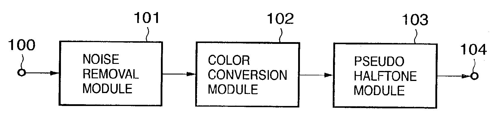
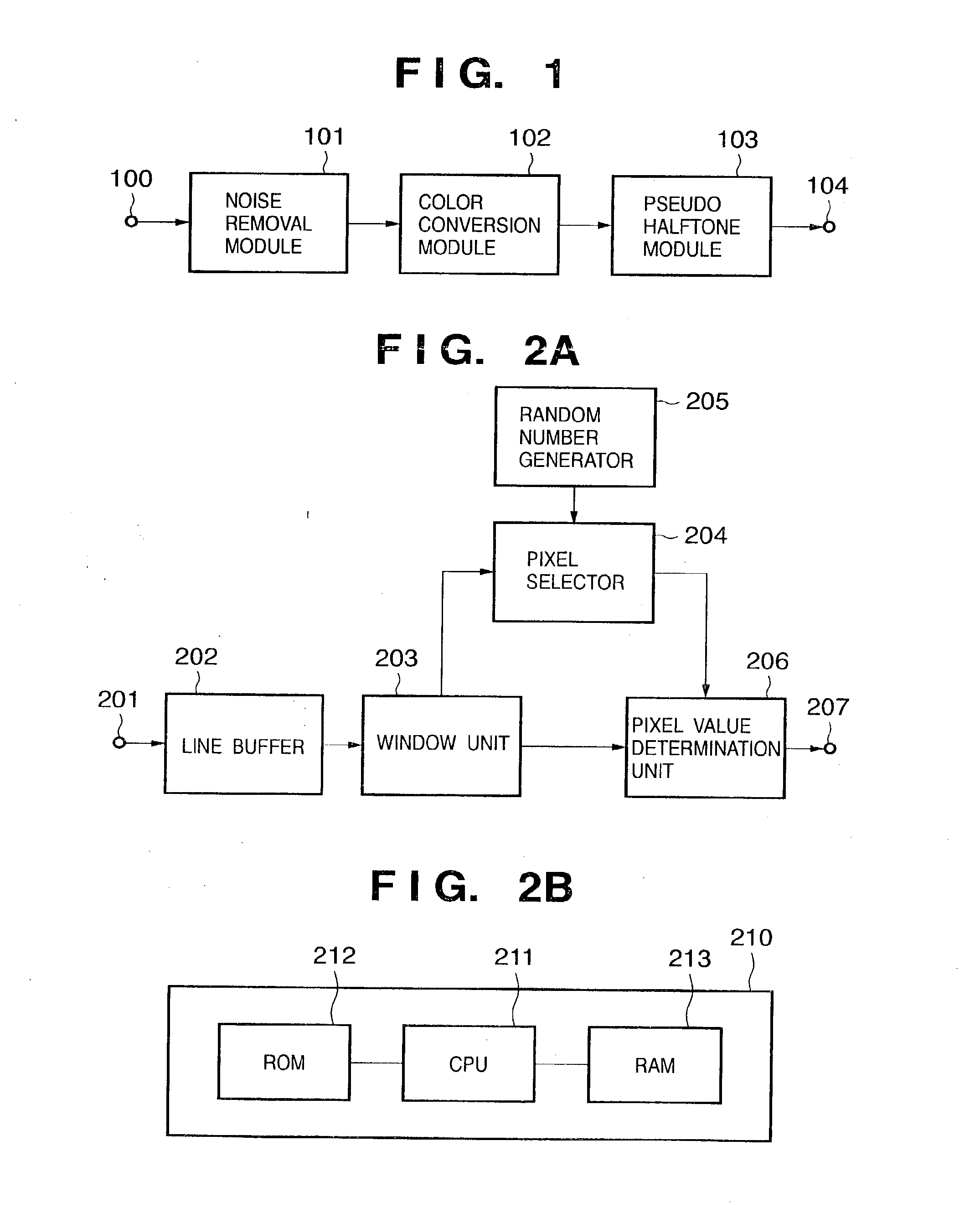
[0072]FIG. 1 is a block diagram showing the arrangement of an image processing apparatus which is implemented by applying a low-frequency noise function according to the present invention to a printer driver that generates print information to be output to a printer engine on ...

second embodiment

[0110]FIG. 11 is a flow chart for explaining the operation sequence of a noise removal module according to the second embodiment of the present invention. Note that the arrangements of the image processing apparatus and noise removal module according to the second embodiment are the same as those in the block diagrams shown in FIGS. 1 and 2. In the second embodiment, a color space on which the noise removal module 101 executes noise removal is a YCrCb color space as a luminance-color difference space in place of the RGB color space.

[0111]Note that conversion from R, G, and B into Y, Cr, Cb is not the gist of the present invention, and a description thereof will be omitted. Therefore, the RGB space may be converted into the YCrCb space before input to the noise removal module 101, or YUV signals as luminance and color difference signals decoded by the JPEG algorithm may be used intact.

[0112]As shown in FIG. 11, the noise removal module 101 resets variable i indicating a vertical proc...

third embodiment

[0140]FIG. 14 is a flow chart for explaining the operation sequence of a noise removal module according to the third embodiment of the present invention. Note that FIG. 14 shows another example of the operation sequence of the noise removal module 101 shown in FIG. 2.

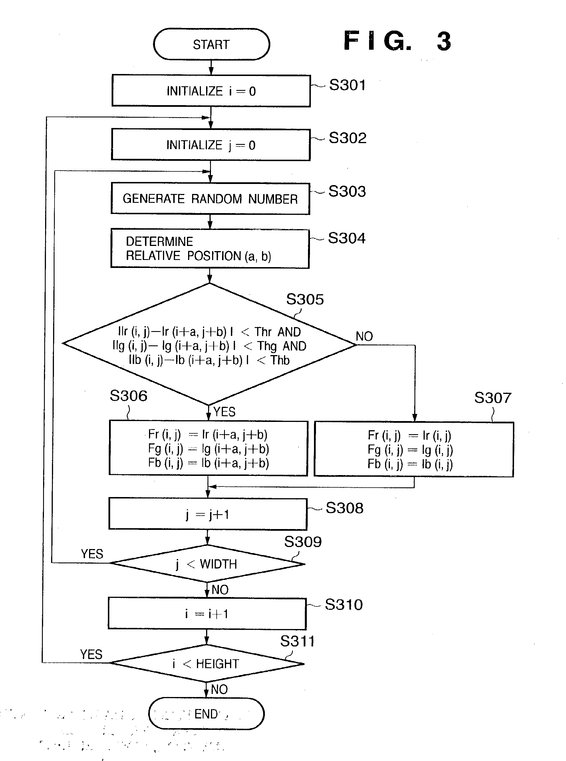
[0141]As shown in FIG. 14, the noise removal module is initialized to reset variable i indicating a vertical processing address to zero (step S1401). Likewise, variable j indicating a horizontal processing address is reset to zero (step S1402). Also, a loop count is initialized to reset variable loop indicating a selectable loop count per pixel of interest (step S1403).

[0142]The random number generator 205 generates a random number (step S1404). The pixel selector 204 determines the values of horizontal and vertical relative positions a and b from the pixel of interest on the basis of the generated random number (step S1405). Using the determine values a and b, comparison is made (step S1406) to see whether or not:

|Ir(i...


PUM


Abstract

This invention provides an image processing apparatus, image processing method, and computer program, which can visually remove low-frequency noise contained in image data. Image data containing low-frequency noise is input from an input terminal (201). A window unit (202) designates a window made up of a pixel of interest, and its surrounding pixels. A pixel selector (204) selects a selected pixel to be compared with the pixel of interest from the window, and a pixel value determination unit (206) determines a new pixel value of the pixel of interest on the basis of the pixel values of the selected pixel and pixel of interest. New image data is generated by substituting the pixel value of the pixel of interest by the new pixel value.

Description

FIELD OF THE INVENTION[0001]The present invention relates to an image processing apparatus and image processing method, and a computer program, which can visually remove noise components from image data on which noise components that are not contained in the original signal components are superposed.BACKGROUND OF THE INVENTION[0002]Conventionally, a technique for removing noise components from a digital image on which noise components that are not contained in the original signal components are superposed has been studied. The characteristics of noise to be removed are diverse depending on their generation causes, and noise removal methods suited to those characteristics have been proposed.[0003]For example, when an image input device such as a digital camera, image scanner, or the like is assumed, noise components are roughly categorized into noise which depends on the input device characteristics of a solid-state image sensing element or the like and input conditions such as an im...

Claims


Application Information

Patent Timeline
Patent Type & Authority Applications(United States)
IPC IPC(8): G06K9/40H04N1/409H04N5/21G06T5/00
CPCH04N1/409G06T5/20G06T5/002
Inventor MIYAKE, NOBUTAKAKUSAKABE, MINORU
Owner CANON KK
Why Eureka
Try Eureka