

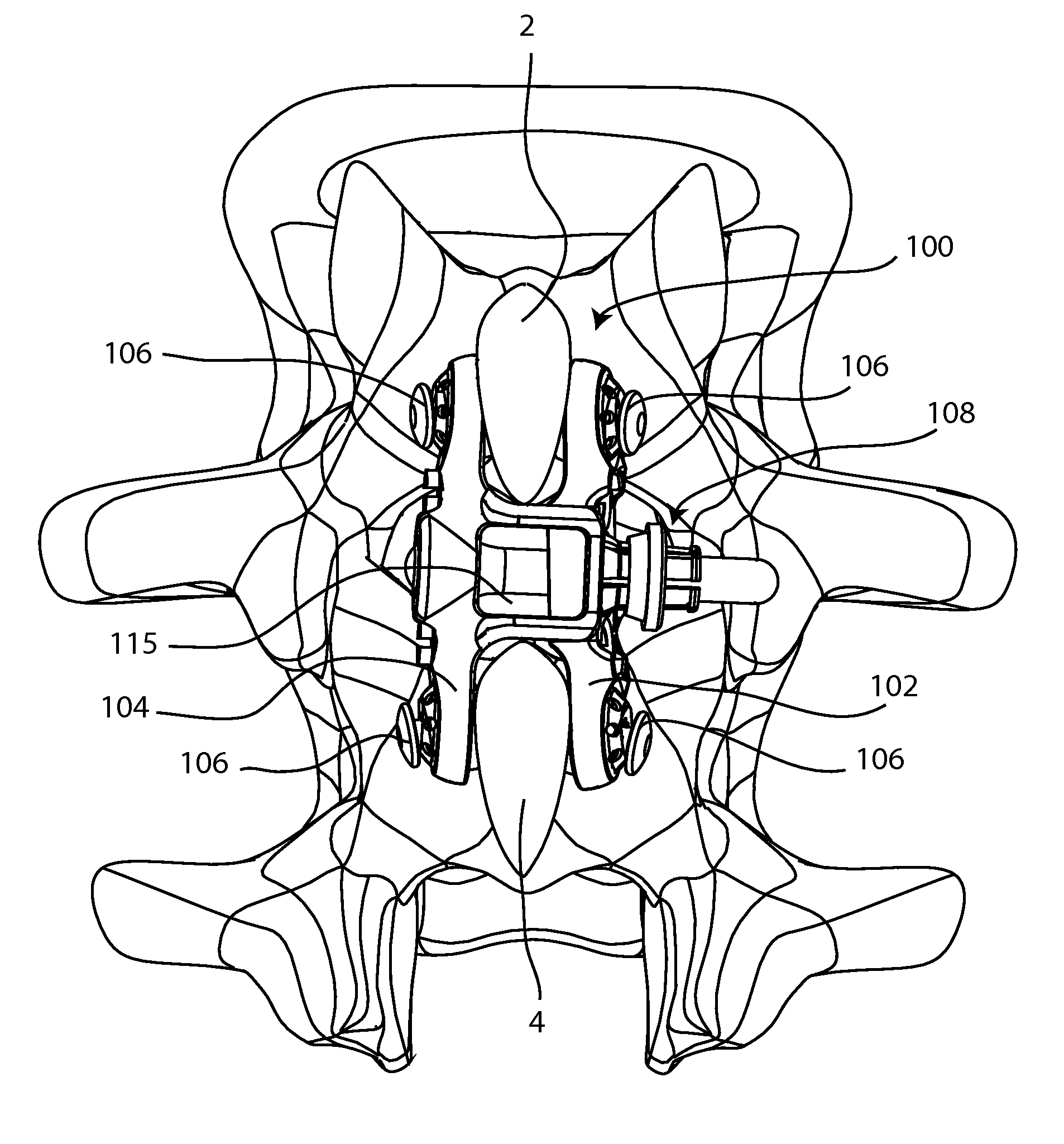
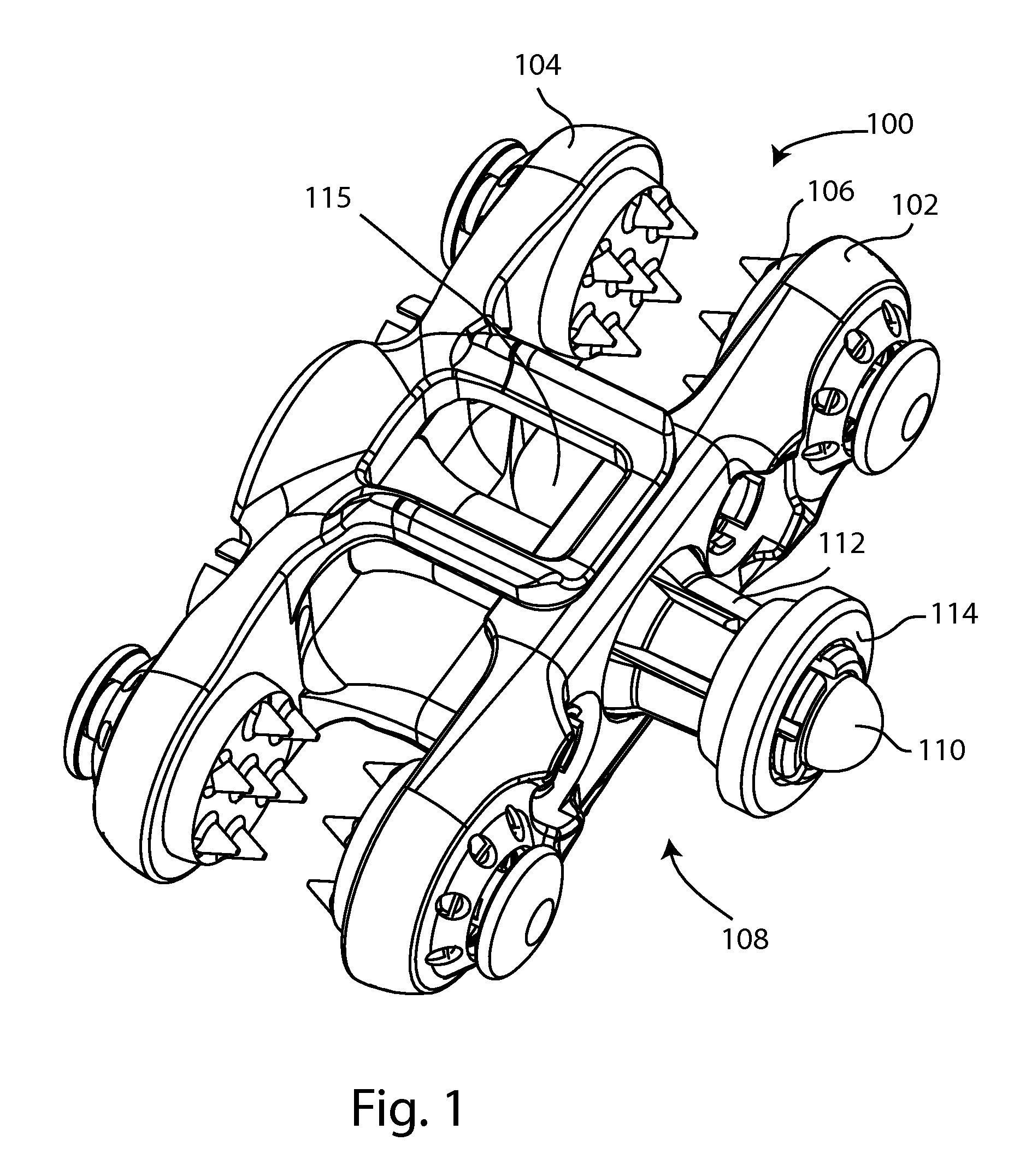
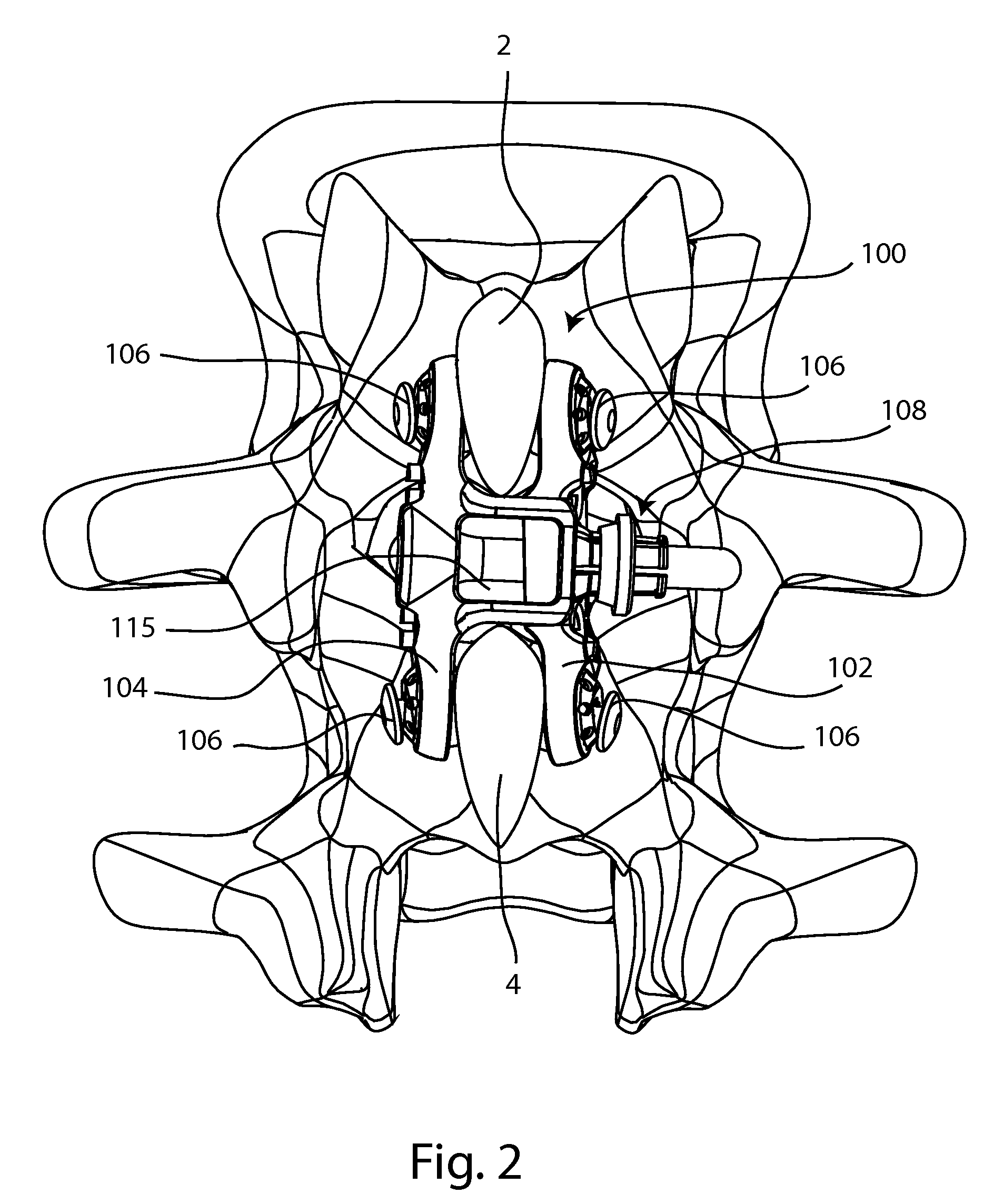
Spinous process fusion implants and insertion, compression, and locking instrumentation
a technology of fusion implants and spinous process, applied in the field of bone fusion procedures, can solve the problems of high potential for irregular fragments, difficulty in securely fitting a bone plate to the bone surface, and irregular cut surfa
- Summary
- Abstract
- Description
- Claims
- Application Information
AI Technical Summary
Problems solved by technology
Method used
Image

Examples
Embodiment Construction
[0070]While exemplary embodiments of the present invention have been shown and described in detail below, it will be clear to the person skilled in the art that changes and modifications may be made without departing from the scope of the invention. As such, that which is set forth in the following description and accompanying drawings is offered by way of illustration only and not as a limitation. The actual scope of the invention is intended to be defined by the following claims, along with the full range of equivalents to which such claims are entitled.
[0071]In addition, one of ordinary skill in the art will appreciate upon reading and understanding this disclosure that other variations for the invention described herein can be included within the scope of the present invention.
[0072]In the following Detailed Description, various features are grouped together in several embodiments for the purpose of streamlining the disclosure. This method of disclosure is not to be interpreted ...
PUM
 Abstract
Description
Claims
Application Information