Support structure for electronic visual display device

a technology of electronic visual display and support structure, which is applied in the direction of rack disposition, vehicle components, transportation and packaging, etc., can solve the problems of limiting the display attached to the back of the headrest by a strap, no option, and difficult to universalize the electronic display support devi

Inactive Publication Date: 2012-01-12
PROCTOR JEFF JAMES +1
View PDF13 Cites 43 Cited by
  • Summary
  • Abstract
  • Description
  • Claims
  • Application Information

AI Technical Summary

Benefits of technology

[0014]In accordance with a preferred embodiment of the invention, there is disclosed a support structure for electronic visual display device comprising: a pair of attachment members each having a vertically disposed aperture that allows the post of a standard passenger vehicle headrest to pass through, each said attachment member being formed of two opposing halves that are held together by screws thereby fixedly attaching said attachment members to said headrest posts, each said attachment member having a horizontally disposed aperture, each said attachment member having a threaded shaft terminating in a locking knob, said threaded shaft capable of penetrating said horizontally disposed aperture, a first rigid extension rod, a second rigid extension rod, a first joint member, a second joint member, a rigid flat electronic device support plate, said first extension member being L shaped, one end of said first extension member end protruding through said horizontally disposed apertures in said headrest post attachment members, the opposite end of said first extension rod terminating in a ball shaped member, said second extension rod terminating at each end in a ball shaped member, said support plate having a ball shaped member fixed to its underside, said support plate being a similar size to the top dimensions of said electronic visual display device, said support plate having at least one standard spring biased clamping member capable of removably retaining at least one side edge of said visual display device, each said joint member comprised of rigid opposing halves, said opposing halves each having ball retaining shapes at each end, said first and second joint members also each having a centrally located threaded post terminating in a knob, said post protruding through a centrally located aperture in one said half of said joint member and threading into a centrally located aperture in the opposing half of said joint member, and said joint members capable of clamping on said ball shaped members when said knobs are turned in a clockwise direction causing said extension rods and said support plate to be locked in a desirable location until unlocked by turning said knobs in a counter clockwise direction.

Problems solved by technology

Although the above patents describe display attachment means, they have certain deficiencies.
The problem with center console mounted designs is that the shape and size of the center console varies from vehicle to vehicle making it hard for the electronic display support device to be universal.
The one patent that shows a display attached to the back of a headrest by a strap is limiting in that there is only one location that the display can be viewed in.
There is no option to place the display in a desired location and then to lock the support device so that the display stays in the desired location.
Additionally, none of the prior art teaches a design for an electronic display support structure that can be easily adjusted to allow viewing by a person sitting in a front seat or a person sitting in a rear seat.
Finally, none of the prior art shows that ability for the support structure to be stored, while still attached to a portion of the vehicle, so that it is completely out of the way when not in use.

Method used


Image

  • Support structure for electronic visual display device
  • Support structure for electronic visual display device
  • Support structure for electronic visual display device

Examples


Embodiment Construction

[0025]Detailed descriptions of the preferred embodiment are provided herein. It is to be understood, however, that the present invention may be embodied in various forms. Therefore, specific details disclosed herein are not to be interpreted as limiting, but rather as a basis for the claims and as a representative basis for teaching one skilled in the art to employ the present invention in virtually any appropriately detailed system, structure or manner.

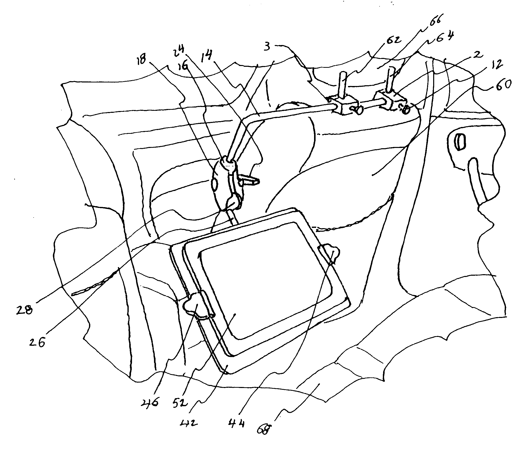
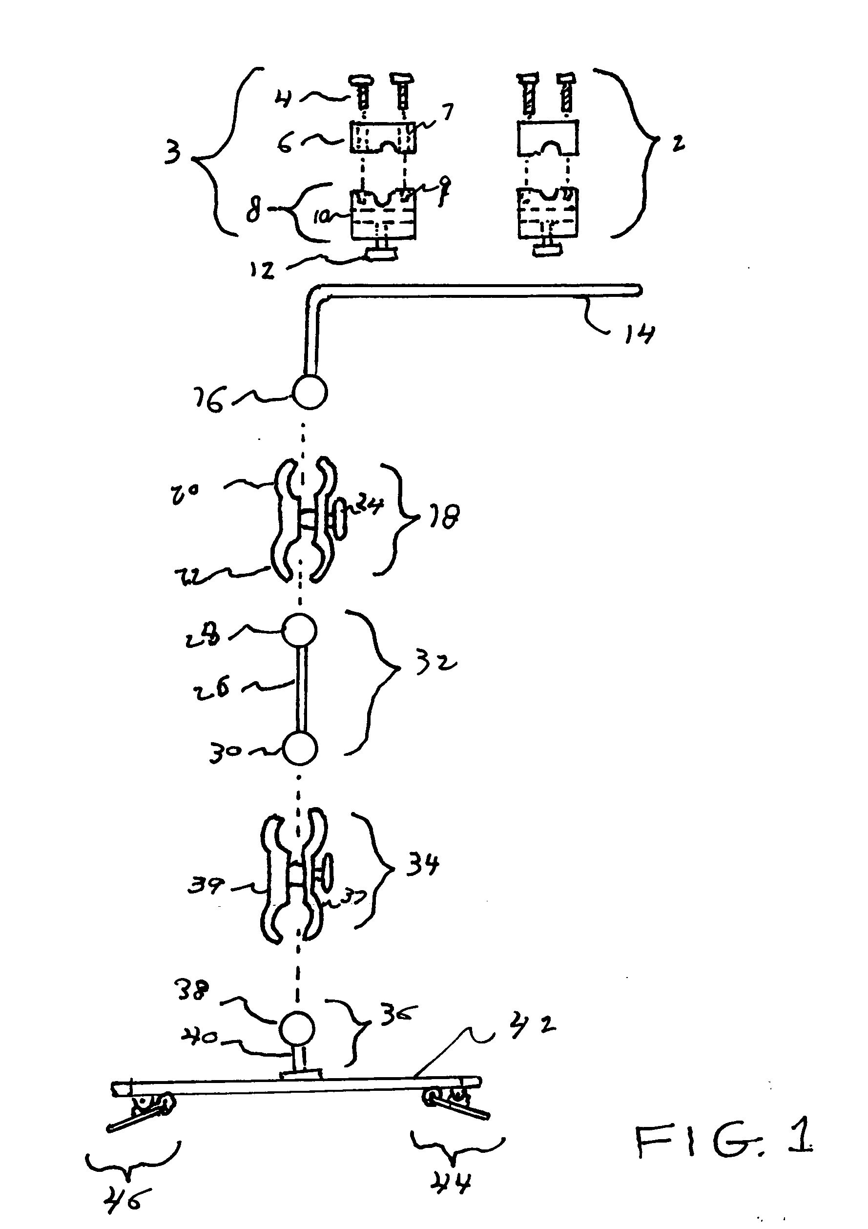
referring now to FIG. 1 we see an exploded view of the components of the present invention. Headrest post clamping members 2, 3 are each comprised of a first half 8 and a second half 6 which can be joined together by threaded screws 6 traveling through apertures 7 and threaded into threaded portions 9. In this way, the clamping members 2, 3 can be attached to headrest posts that do not easily disengage from the top portion of the seat back of a standard vehicle passenger seat. Horizontal apertures 10 allow the long side of L shaped r...


PUM


Abstract

A support structure for an electronic visual display device with a pair of vehicle head rest post clamping members, a first and second extension rod, a first and second joint member and an electronic device support plate. The first extension member is L shaped. One end end protrudes into and locks to the headrest post attachment members. The opposite end terminates in a ball shaped member. The second extension rod terminates at each end in a ball shaped members. The support plate has a ball shaped member fixed to its underside. The joint members connect the first and second extension rods to the underside of the support plate. The plate has a clamping member that can retain the visual display device. The joint members clamp on the ball shaped members when joint locking knobs are turned allowing the display to be positioned in a desired location.

Description

CROSS REFERENCE TO RELATED APPLICATIONS[0001]Not ApplicableSTATEMENT REGARDING FEDERALLY .SPONSORED RESEARCH OR DEVELOPMENT[0002]Not ApplicableDESCRIPTION OF ATTACHED APPENDIX[0003]Not ApplicableBACKGROUND OF THE INVENTION[0004]This invention relates generally to the field of vehicle accessories and more specifically to a support structure for electronic visual display device to be used in passenger vehicles.Portable visual electronic display devices have become very popular in recent years. These devices include lap top computers, portable DVD players and graphically enhanced cell phones. Recently, the I Pad product has been introduced by Apple Computer Company. This product is a tablet shaped device that can display everything from the pages of the New York Times to anything that can be downloaded off the Internet, including full length movies. Most of the time, users simply hold the electronic display device in his or her hands and views the displayed material at arms length.Howe...

Claims


Application Information

Patent Timeline
Patent Type & Authority Applications(United States)
IPC IPC(8): B60R7/08
CPCB60R11/02B60R2011/0017B60R2011/0089B60R2011/0071B60R2011/0059
Inventor PROCTOR, JEFF JAMESHUEGERICH, DAVID THOMAS
Owner PROCTOR JEFF JAMES
Why Eureka
Try Eureka