Wiper arm for a windscreen wiper

a technology of windscreen wiper and wiper arm, which is applied in the field of wiper arms, can solve the problems of affecting the operation of the vehicle, so as to prevent damage to the hood, facilitate installation, and ensure the effect of good use

Inactive Publication Date: 2005-11-15
ROBERT BOSCH GMBH
View PDF14 Cites 35 Cited by
  • Summary
  • Abstract
  • Description
  • Claims
  • Application Information

AI Technical Summary

Benefits of technology

[0008]According to the invention, between the operating position and the swing-down position, a detent position is provided, up to which the wiper blade can be raised from the windshield in a parking position, without touching an engine hood. For installing a wiper blade, the windshield wiper is moved out of the parking position into a mounting position, in which without damaging the hood the detent position can be bridged, and the joint member reaches the swing-down position with a swing-down angle in which the wiper blade can easily be installed. In the parking position, the joint member is fixed in an intermediate position that precludes damage to the hood but at the same time offers sufficient free space for cleaning the wiper blade or the windshield. This position is advantageously embodied as a detent position, so that the wiper arm can be securely kept in this position, in which it does not unintentionally strike the hood or fall back against the windshield again without the wiper blade being in place.
[0009]To make the detent position of the windshield wiper possible, it is advantageous that only slight changes in the usual standard components are needed. On its end toward the joint member, the fastening part of the invention has a detent path, which is expediently formed on in the course of production of the fastening part. As a modification compared with the standard component, a spring detent is secured to the joint member. The spring detent is expediently disposed in the spring chamber of the joint member, specifically laterally offset from the C-shaped bracket or from the tension spring.

Problems solved by technology

Thus under the force of the tension spring, the wiper blade rests on the windshield and is limited by it in its operating position.
In this swing-down position, which does suffice to clean the windshield but makes changing the wiper blade more difficult, the joint member is held by a spring detent that is formed by the tension spring and a cam-shoulder assembly.
In the preassembled state, for instance for shipping, there is the risk that a slight exertion of force on the premounted wiper arm, for instance from jarring during shipping or from careless handling, the pivot shaft will slide out of the hub, and the swing-down joint will fall apart into its individual components.
This necessitates additional installation work and has the risk the parts will be lost.

Method used


Image

  • Wiper arm for a windscreen wiper
  • Wiper arm for a windscreen wiper
  • Wiper arm for a windscreen wiper

Examples


Embodiment Construction

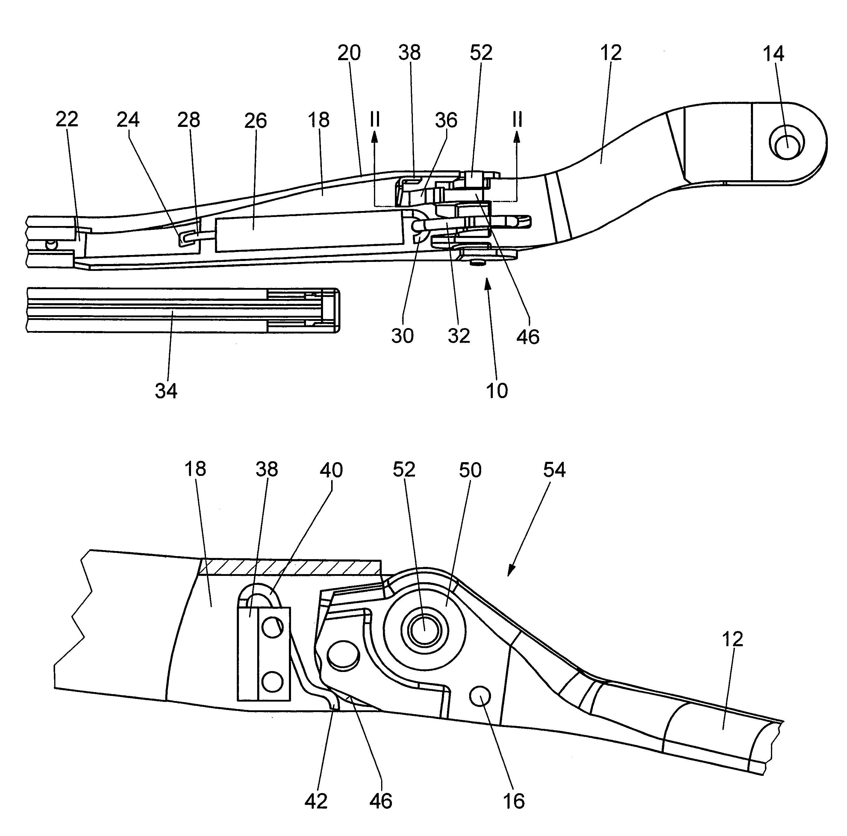
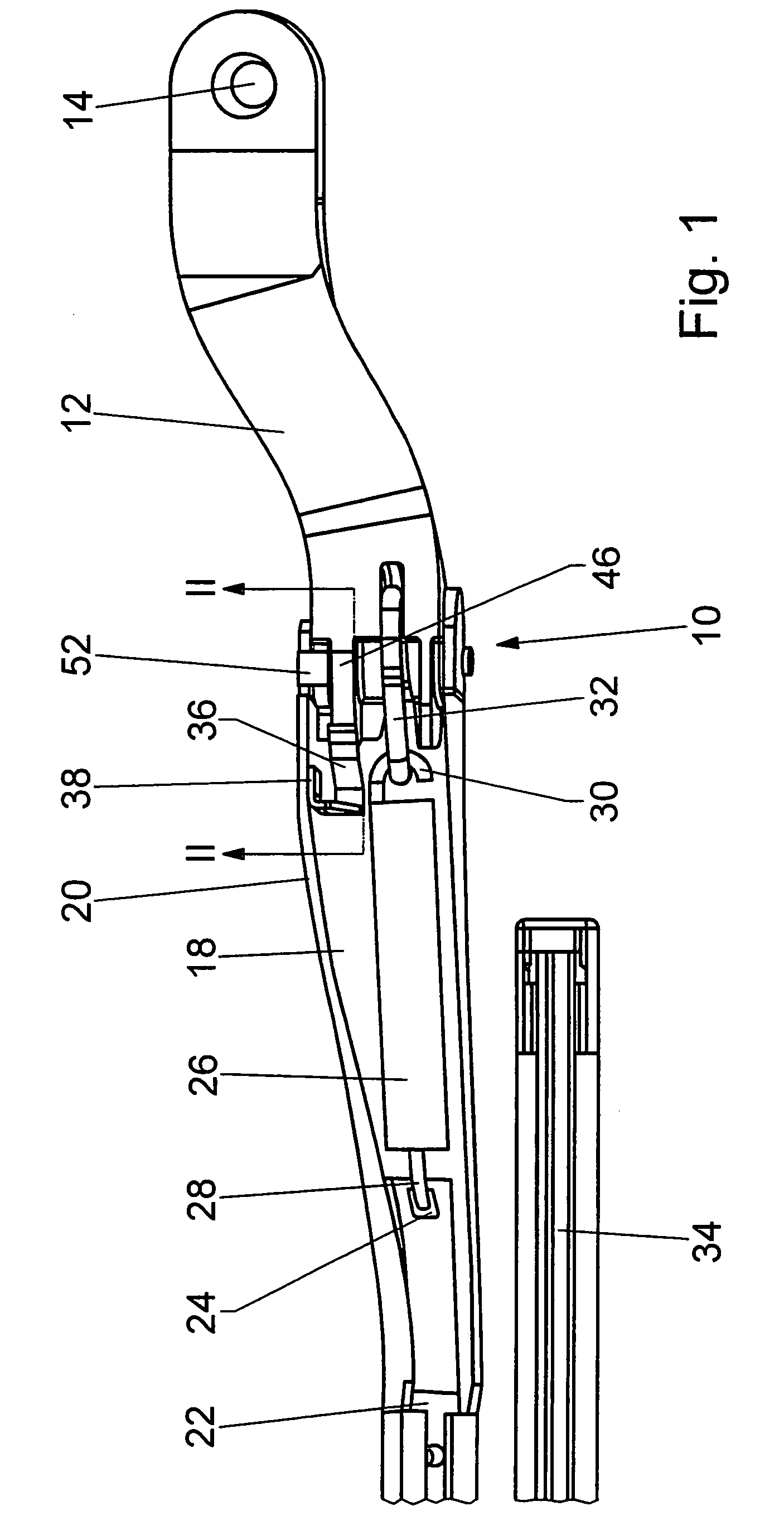
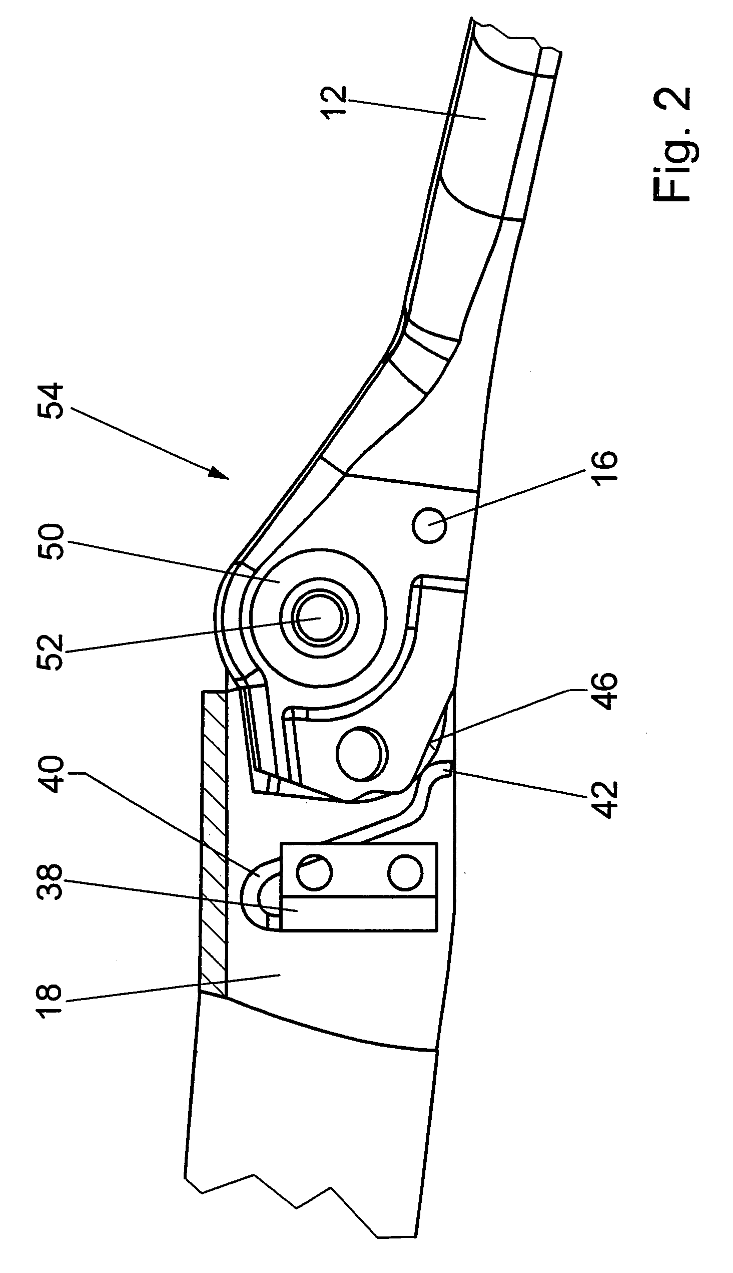
[0017]A wiper arm 10 includes a fastening part 12 and a joint member 18, with a wiper rod 22 to which a wiper blade 34 is pivotably connected (FIG. 1). On one end, the fastening part 12 has a receiving bore 14 for a drive shaft, not shown, of the windshield wiper. On its other end, the fastening part 12 is pivotably connected to the joint member 18 by a swing-down joint 54. In the operating position shown, both parts are braced against one another by a tension spring 26. To that end, the tension spring 26 is suspended by one end 28 from an angle element in the form of a suspension eye 24 on the wiper rod 22 and by its other end 30 via a C-shaped bracket 32 from an angle element in the form of a transverse pin 16 on the fastening part 12 (FIG. 2).

[0018]In the region of the swing-down joint 54, the joint member 18 has a U-shaped cross section, in the interior space of which the tension spring 26 is accommodated. Next to the tension spring 26 and the C-shaped bracket 32, there is a spr...


PUM


Abstract

The invention is based on a wiper arm (10) for a windshield wiper, having a fastening part (12) and a joint member (18) that are connected to one another via a swing-down joint (54), and a tension spring (26) is suspended by one end (28) from a suspension device (24) of the joint member (18) and by its other end (30) via a C-shaped bracket (32) in a suspension device (16) of the fastening part (12) and in an operating position presses a wiper blade (34), via a wiper rod (22), against a windshield and in a swing-down position presses a contact face of the joint member (18) or of the C-shaped bracket (32) against a limiting stop of the fastening part (12). It is proposed that between the operating position and the swing-down position, a detent position is provided, up to which the wiper blade (34) can be raised from the windshield in a parking position, without touching a hood over the engine.

Description

BACKGROUND OF THE INVENTION[0001]The invention is based on a wiper arm for a windshield wiper.[0002]Known windshield wipers have a wiper arm that comprises a fastening part and a joint member that has a wiper rod and is pivotably connected to the fastening part. A wiper blade, which as a rule is constructed of a wiper strip holder and a wiper strip, is pivotably connected to the wiper rod.[0003]The joint member, on its end toward the fastening part, has a spring chamber for a tension spring. The spring chamber is open toward the windshield, and toward the wiper rod it has an angle element, such as an eye, from which a retaining bracket of the tension spring is suspended. The other end of the tension spring engages a C-shaped bracket, which is suspended from an angle element of the fastening part. The C-shaped bracket can also be formed onto the tension spring. The joint member is braced via a hub on a joint pin of the fastening part. The joint thus formed, also called a swing-down j...

Claims


Application Information

Patent Timeline
Patent Type & Authority Patents(United States)
IPC IPC(8): B60S1/32B60S1/34
CPCB60S1/3413B60S1/32
Inventor KNAUF, RICHARD
Owner ROBERT BOSCH GMBH
Why Eureka
Try Eureka