
Joint brace with multi-planar pivoting assembly and infinitely adjustable limb extension regulator

a multi-planar, adjustable technology, applied in the field of joint braces, can solve problems such as proper joint car

Inactive Publication Date: 2005-11-08
ASTERISK ASTERISK
View PDF72 Cites 38 Cited by
  • Summary
  • Abstract
  • Description
  • Claims
  • Application Information

AI Technical Summary

Benefits of technology

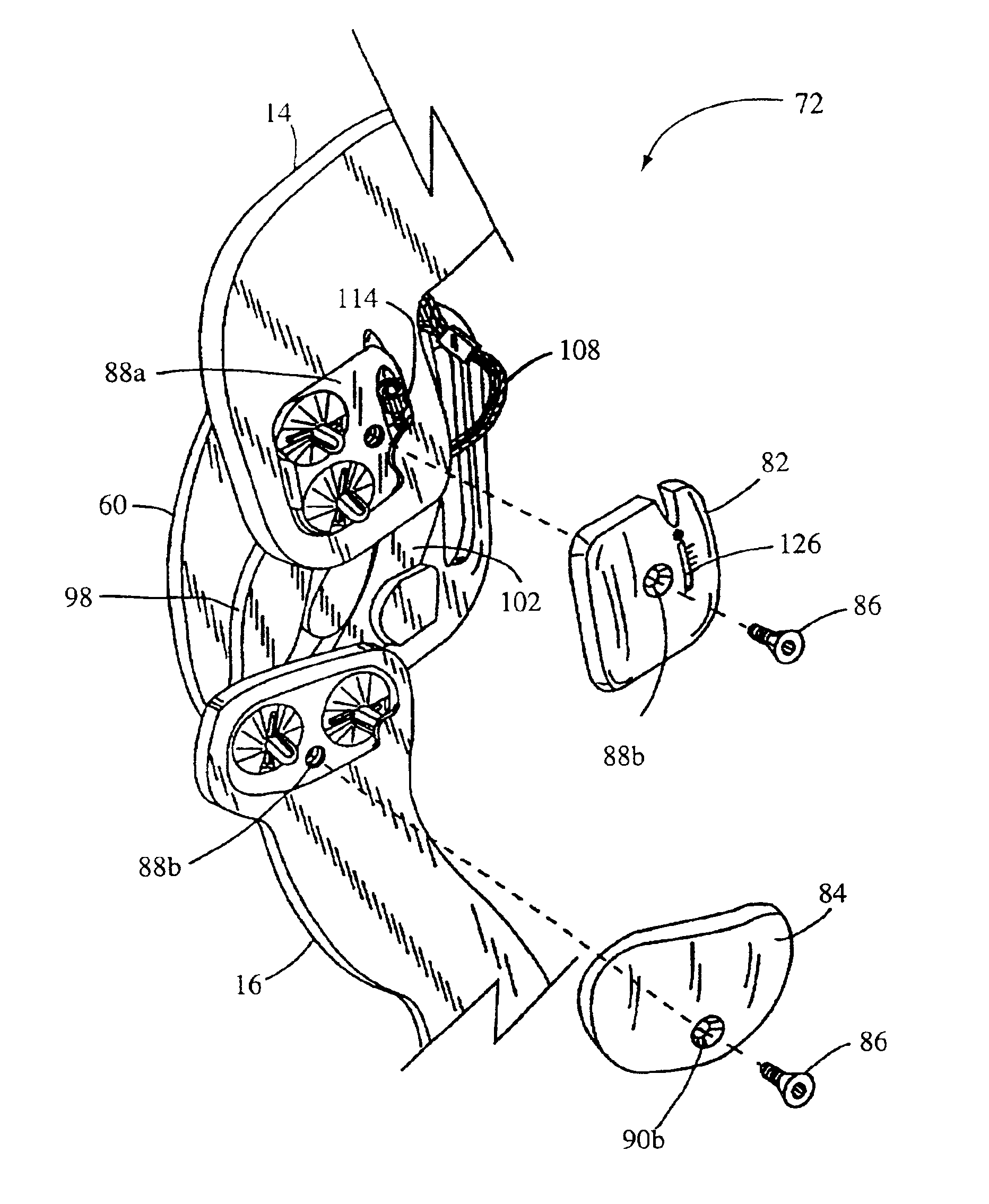
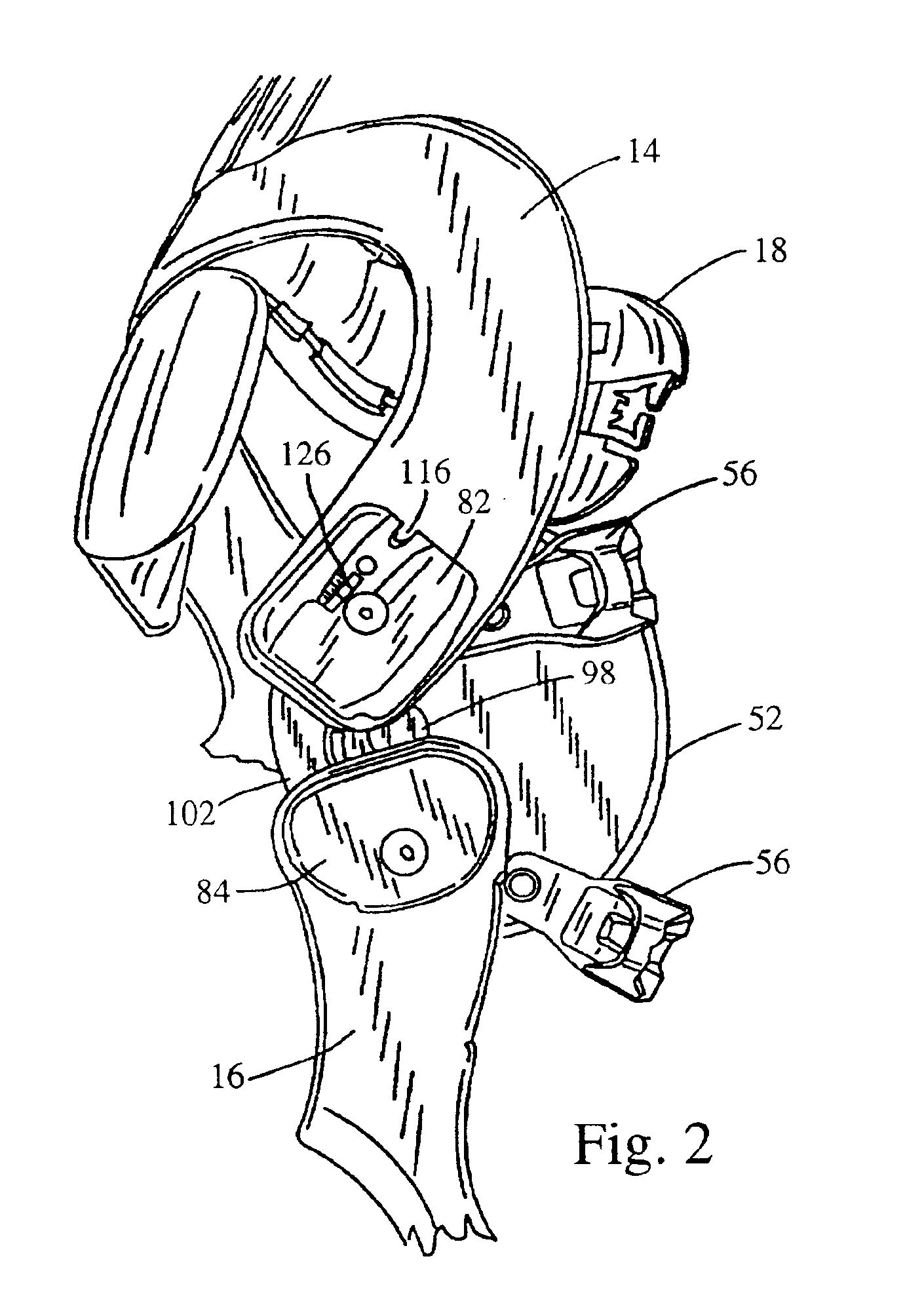
[0008]The present invention is an exteriorly positionable anatomical brace for stabilizing a uniting pivoting joint such as a knee joint disposed between a first and second limb structure of a living being. The brace comprises an upper frame member and a lower frame member joined together by a pivoting joint member, with each such frame member having secured thereon a respective cuff for encompassing a portion of each limb structure above and below the joint. Retention of the brace in place at the joint site is preferably accomplished with respective upper and lower securement members each wrapping around a respective limb structure in alignment with and not encompassed by the cuff. The pivoting joint member comprises two opposing pivoting assemblies each positionable on one side of the anatomical joint of a wearer to thus join the upper and lower frame members together. Each of these assemblies includes a forward arm member and a rearward arm member each having an upper end and a lower end, with these ends connected respectively to the upper frame member and the lower frame member. Specifically, the upper ends of each arm are individually mounted within a spherically-pivotal socket in connection with the upper frame member, while the lower ends of each arm likewise are individually mounted within a spherically-pivotal socket in connection with the lower frame member. As is apparent, these individual spherical mounts permit the selection of differing pivot ratios at a total of eight sites (four sites per lateral and per medial side) to thereby enable the upper and lower frame members to assume many different angular relationships with each other. Because of the availability of such a vast number of relationship combinations, the frame members of the brace becomes substantially self-aligning with each individual joint encounter among many wearers, thus accomplishing simulation of actual limb movement and angular interrelations thereof as natural individual limb-structure correlations are maintained.

Problems solved by technology

As earlier noted, proper joint care many times requires limited or regulated limb extension, with such control emanating at the pivoting joint member.

Method used


Image

  • Joint brace with multi-planar pivoting assembly and infinitely adjustable limb extension regulator
  • Joint brace with multi-planar pivoting assembly and infinitely adjustable limb extension regulator
  • Joint brace with multi-planar pivoting assembly and infinitely adjustable limb extension regulator

Examples


Embodiment Construction

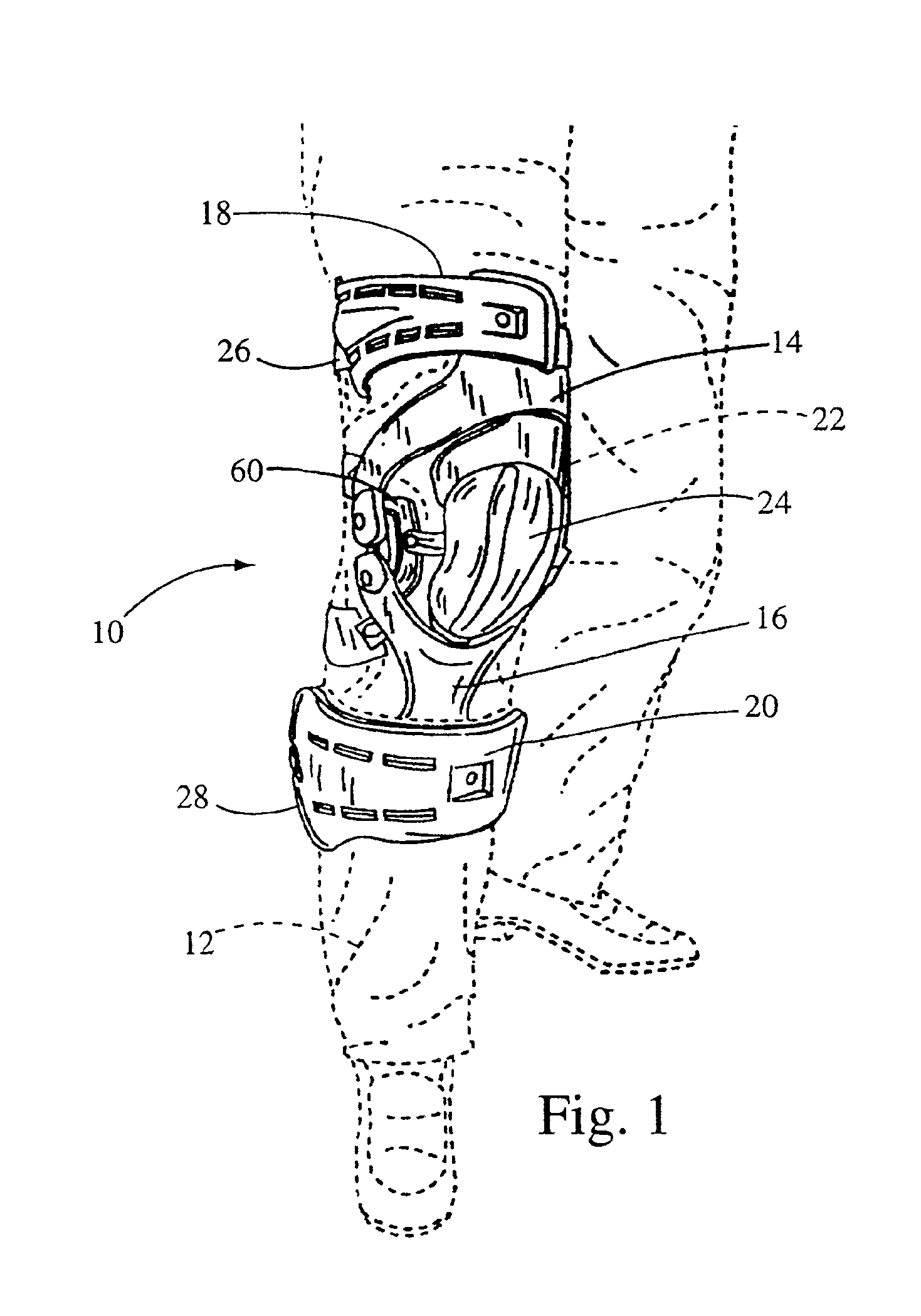
[0024]Referring first to FIGS. 1-5, a knee brace 10 is shown (FIG. 1) in place on a leg 12 of a human being. The brace 10 has an upper frame member 14 and a lower frame member 16, with each such frame member 14, 16 having secured thereon a respective cuff 18, 20 for disposition about the limb structures above and below the knee joint 22. Each cuff 18, 20 is an arcuate wall structure, which non-limitedly can be fabricated of a polymer plastic, for juxtapositioning with the respective limb structures as shown. A snap-in protective patella cup 24 can be included as shown for specific impact absorption that may occur at the patella of the knee joint 22.

[0025]The knee brace 10 is retained in place on the leg 12 with respective upper and lower securement members 26, 28 each respectively wrapping around an adjacent rear portion of the leg 12. While FIGS. 2-5 show only the upper securement member 26, it is to be understood that the following description thereof applies equally to the lower ...


PUM


Abstract

A brace for stabilizing a joint such as a knee disposed between a first and second limb structure. The brace includes upper and lower frame members, cuffs for encompassing a portion of each limb structure, and a uniting pivoting joint member. The joint member includes two opposing pivoting assemblies, with each including a forward and a rearward arm member each having upper and lower ends spherically-pivotally connected to the upper and lower frame members for enabling multiple angular relationships. The pivoting assembly can include a limb extension regulator, preferably a cable, extending between the rearward arm member and the upper frame member to permit infinitely adjustable extendability of the brace-bearing limb. Most preferably, a visible measurement scale is provided for precise extension distances.

Description

CROSS REFERENCE TO RELATED APPLICATIONS[0001]This application is a continuation-in-part of U.S. patent application Ser. No. 09 / 776,523, filed Feb. 2, 2001.STATEMENT RE: FEDERALLY SPONSORED RESEARCH / DEVELOPMENT[0002]Not ApplicableBACKGROUND OF THE INVENTION[0003]This invention relates in general to braces for joint support, and in particular to an exteriorly positionable anatomical brace having a pivoting joint assembly with multi planar hinging for accurate alignment of joined limb structures in relation to each other, and additionally having an infinitely-adjustable, cable-controlled limb extension regulator.[0004]Both injury and disease can affect the health, well-being, and operability of various joints of the human body. Chief among such joints are the knee and elbow where disease such as osteo-arthritis can curtail normal activity or where an injury such as a sports-related abuse or impact can prevent or severely limit continued activity. One manner of treating such joint condi...

Claims


Application Information

Patent Timeline
IPC IPC(8): A61F5/01
CPCA61F5/0123A61F2005/0167
Inventor CASTILLO, JAMES
Owner ASTERISK ASTERISK
Learn More