Dual end cap for a seal assembly

a sealing assembly and dual technology, applied in the direction of roofs, doors, transportation and packaging, etc., to achieve the effect of less prone to vibrational impa

Inactive Publication Date: 2014-02-06
HENNIGES AUTOMOTIVE SEALING SYST NORTH AMERICA
View PDF15 Cites 4 Cited by
  • Summary
  • Abstract
  • Description
  • Claims
  • Application Information

AI Technical Summary

Benefits of technology

[0009]The seal assembly also has a dual end cap disposed between the first seal and the second seal. The dual end cap has a body disposed between the first distal end of the first seal and the third distal end of the second seal. The body has a first side facing the first distal end of the first seal, and a second side opposite the first side facing the third distal end of the second seal. The first side and the second side terminate at an edge. The dual end cap also has a cover attached to a portion of the edge. The cover extends beyond the first side and the first distal end of the first seal and extends beyond the second side and the third distal end of the second seal. The cover provides an aesthetic transition between the first seal and the second seal. The dual end cap also has a first projection extending traverse from the first side and disposed in the channel of the first seal for coupling the dual end cap to the first seal. The dual end cap also has a hold down feature extending traverse from the second side opposite the first projection. The hold down feature engages at least a portion of the third distal end of the second seal such that the portion of the third distal end is sandwiched between the cover and the hold down feature for securing the dual end cap to the second seal.
[0010]The present invention further provides the dual end cap for covering the first distal end of the first seal to the third distal end of the second seal. The first seal defines the channel extending from the first distal end. The dual end cap has the body having the first side and the second side opposite the first side with the first and second sides terminating at the edge. The dual end cap also has the cover attached to the portion of the edge. The cover extends beyond the first and second sides for providing the aesthetic transition between the first distal end of the first seal and the third distal end of the second seal. The dual end cap also has the first projection extending traverse from the first side for extending into the channel of the first seal to couple the dual end cap to the first seal. The dual end cap also has the hold down feature extending traverse from the second side and opposite the first projection. The hold down feature has an engagement end with the dual end cap defining a gap between the cover and the engagement end for receiving at least the portion of the third distal end of the second seal to couple the dual end cap to the second seal.
[0011]Advantageously, the dual end cap is coupled not only to the first seal, but the dual end cap is also coupled to the second seal. As a result of this dual coupling, the dual end cap is less prone to vibrational impact the vehicle while the vehicle is in motion. As such, the dual end cap provides an aesthetic transition between two adjacent seal ends without subjecting the exterior of the vehicle to wear or damage.

Problems solved by technology

While such end caps may successfully provide this pleasing transition, the end caps are only coupled to one of the two adjacent seal ends, and thus, the end caps merely abut the uncoupled seal end.

Method used


Image

  • Dual end cap for a seal assembly
  • Dual end cap for a seal assembly
  • Dual end cap for a seal assembly

Examples


Embodiment Construction

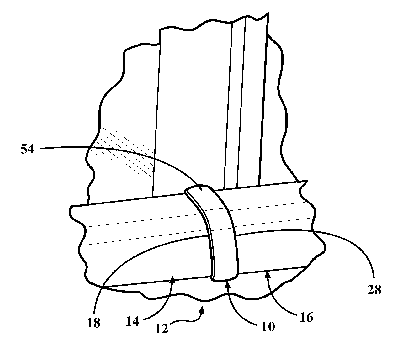
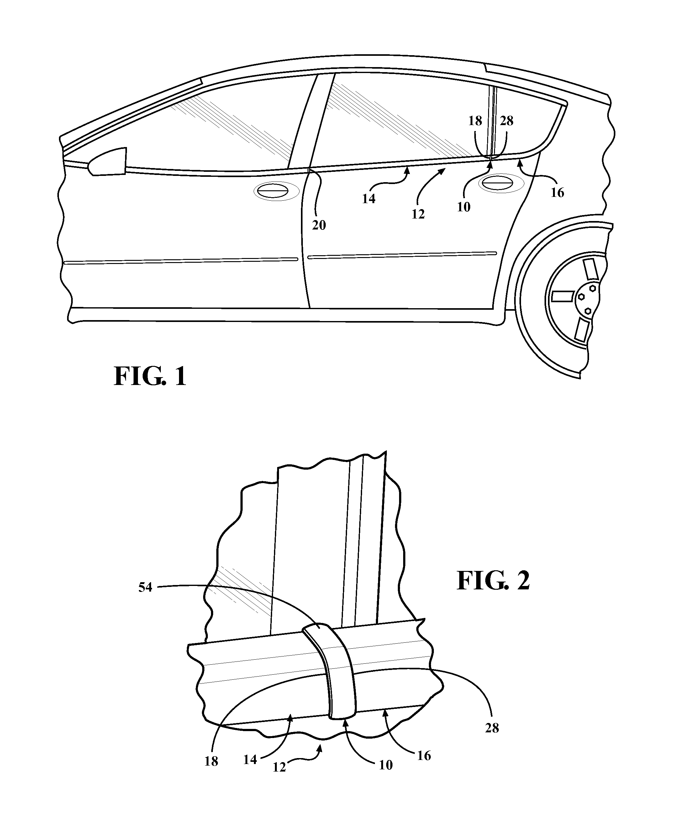
[0023]Referring to the Figures, wherein like numerals indicates like or corresponding parts throughout the several views, a dual end cap 10 for a seal assembly 12 of a vehicle is generally shown. As best shown in FIGS. 1, 2, 8, 9, and 10, the seal assembly 12, includes a first seal 14 for sealing a first window of the vehicle, a second seal 16 for sealing a second window on the vehicle, and the dual end cap 10 for providing an aesthetic transition between the first seal 14 and the second seal 16.

[0024]The first seal 14 is typically produced through an extrusion process and subsequently mounted to the first window. The first window is typically movable. In other words, the first seal 14 is typically an extruded seal that is mounted to the movable window on the vehicle. The first seal 14 typically includes one or more flexible sealing elements or lips which wipingly and sealingly engage the movable window. Although not required, the first seal 14 typically has an arcuately configured ...


PUM


Abstract

A seal assembly for a vehicle having a first seal and a second seal with a dual end cap disposed between the first and second seals. The dual end cap has a cover that extends beyond the first and second seal, for providing an aesthetic transition between the first and second seals. The dual end cap also has a first projection extending from the dual end cap for coupling the dual end cap to the first seal. The dual end cap also has a hold down feature extending opposite the first projection. The hold down feature engages at least a portion of the third distal end of the second seal such that the portion of the third distal end is sandwiched between the cover and the hold down feature for securing the dual end cap to the second seal.

Description

CROSS-REFERENCE TO RELATED APPLICATION[0001]The subject patent application claims priority to and all the benefits of U.S. Provisional Patent Application No. 61 / 678,438 filed on Aug. 1, 2012, which is herein incorporated by reference in its entirety.BACKGROUND OF THE INVENTION[0002]1. Field of the Invention[0003]The invention generally relates to a dual end cap for a seal assembly. More specifically, the invention relates to a dual end cap for a seal assembly where the dual end cap couples to a first seal and a second seal while creating an aesthetic transition between the first and second seal on a vehicle.[0004]2. Description of Related Art[0005]End caps are commonly used in conjunction with a seal on a vehicle. Generally, end caps are configured to close one side of a seal end. Some end caps however, provide a pleasing transition between two adjacent ends of the same seal or two adjacent ends of differing seals. While such end caps may successfully provide this pleasing transitio...

Claims


Application Information

Patent Timeline
Patent Type & Authority Applications(United States)
IPC IPC(8): B60J10/00
CPCB60J10/0091B60J10/2335B60J10/30B60J10/36B60J10/40B60J10/74B60J10/75B60J10/76
Inventor JENDROSSEK, NORBERTCHOLEWA, DIRK
Owner HENNIGES AUTOMOTIVE SEALING SYST NORTH AMERICA
Why Eureka
Try Eureka