

Determining a phase of an object movement in a series of images
- Summary
- Abstract
- Description
- Claims
- Application Information
AI Technical Summary
Benefits of technology
Problems solved by technology
Method used
Image

Examples
Example
DETAILED DESCRIPTION OF THE DRAWINGS
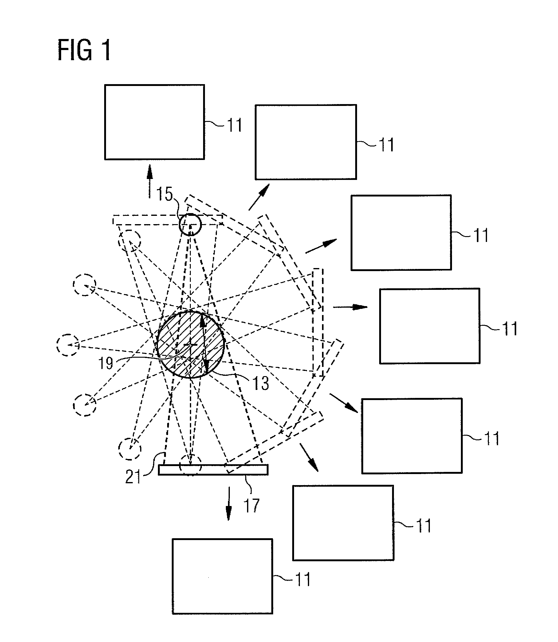
[0038]FIG. 1 shows a schematic diagram of cone beam computed tomography that is used to produce projection images 11 of an object 13 to be examined.
[0039]An x-ray source 15 and an x-ray detector 17 rotate about a common center of rotation 19. The x-ray source 15 directs an x-ray cone beam 21 onto the x-ray detector 17. The x-ray detector 17 is in an eccentric position such that the center of rotation 19 does not lie centrally in the x-ray cone beam 21.
[0040]A plurality of projection images 11 are successively produced by rotating the x-ray source 15 and x-ray detector 17. The plurality of projection images 11 form a series of images of the object 13 to be examined.
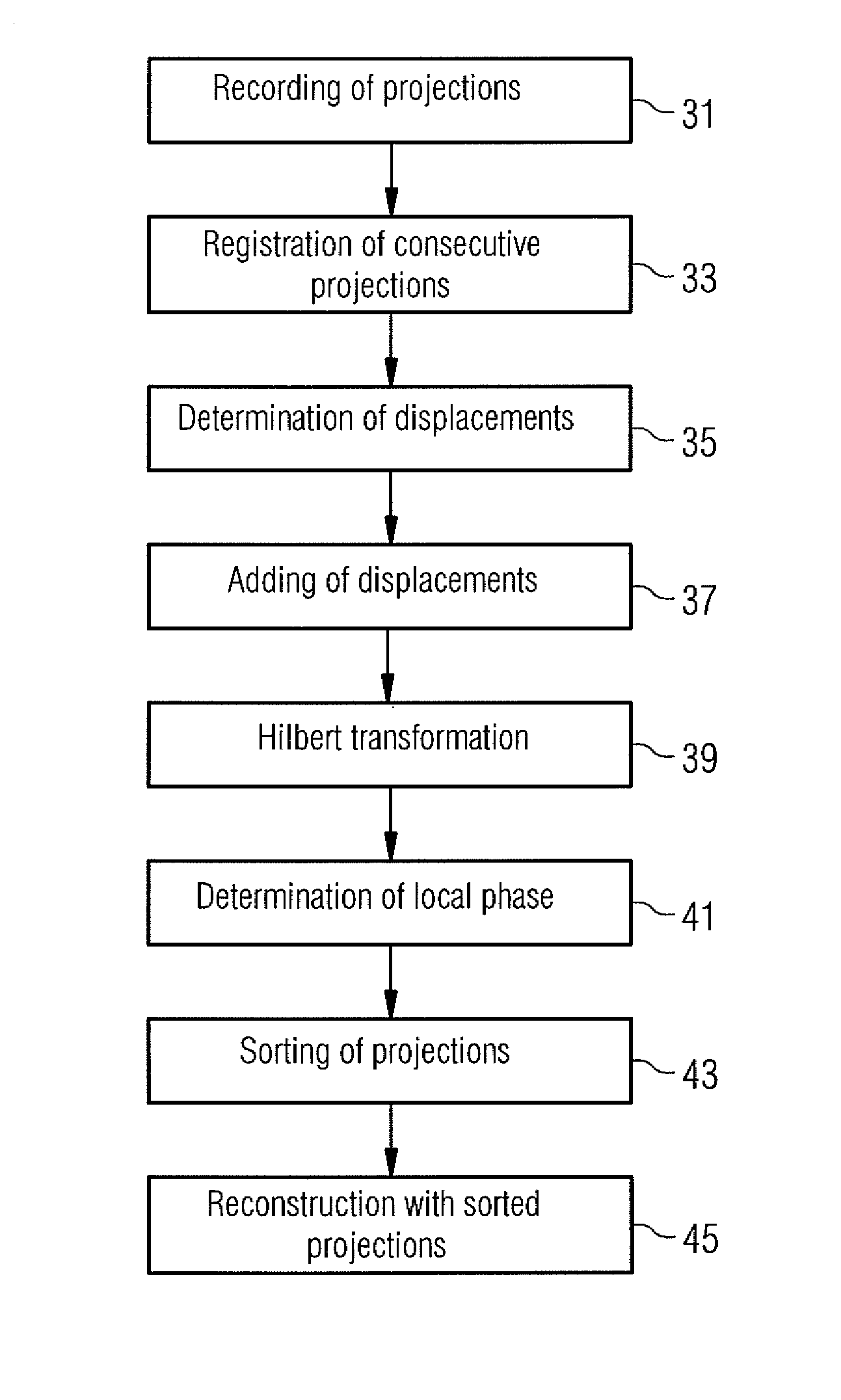
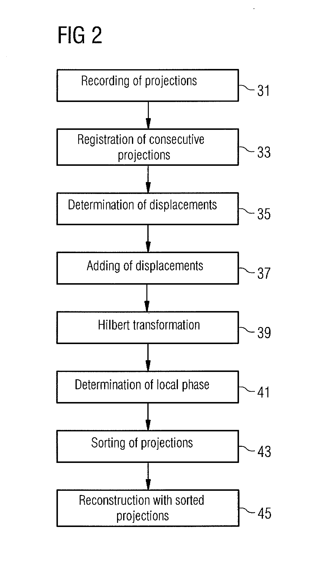
[0041]Because of a movement of the object 13, which is shown by the arrow in FIG. 1, the object may have one movement phase in one projection image and a different movement phase in another projection image. When performing reconstruction, however, it is advantageous to use projection im...
PUM
 Abstract
Description
Claims
Application Information