Backlight device and display apparatus

a backlight device and display device technology, applied in the field of backlight devices and display devices, can solve problems such as flicker disadvantageously occurring under specific conditions, and achieve the effect of improving image quality

Inactive Publication Date: 2012-01-19
PANASONIC CORP
View PDF23 Cites 20 Cited by
  • Summary
  • Abstract
  • Description
  • Claims
  • Application Information

AI Technical Summary

Benefits of technology

[0017]According to the present invention, when a driving duty and a driving current are controlled depending ...

Problems solved by technology

For this reason, even though driving waveform patterns in which the same brightness are obtained are used, in transiti...

Method used


Image

  • Backlight device and display apparatus
  • Backlight device and display apparatus
  • Backlight device and display apparatus

Examples


embodiment 1

[0035]Embodiment 1 of the present invention will be described below.

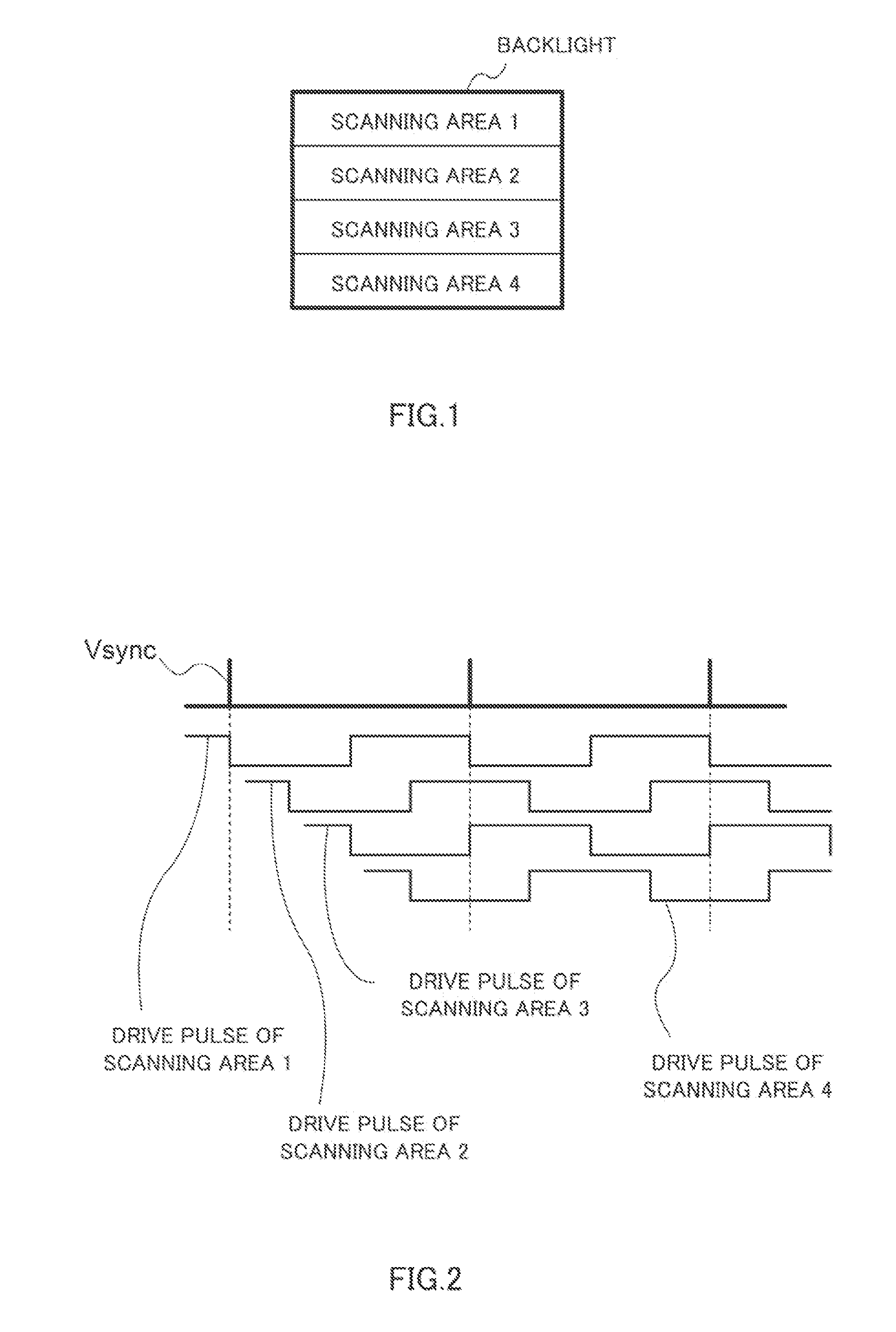
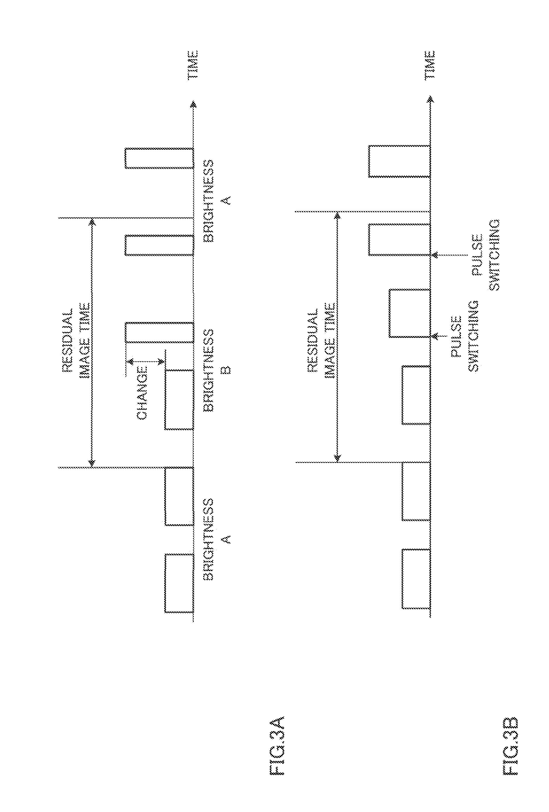
[0036]In the embodiment, a case in which a change in peak value and an updating cycle are suppressed in backlight scanning to prevent flicker upon change of driving waveforms will be described. The backlight scanning, as described above, is a technique that sequentially lights of scanning areas in synchronism with scanning of an image to reduce a residual image (moving image blurring).

[0037]

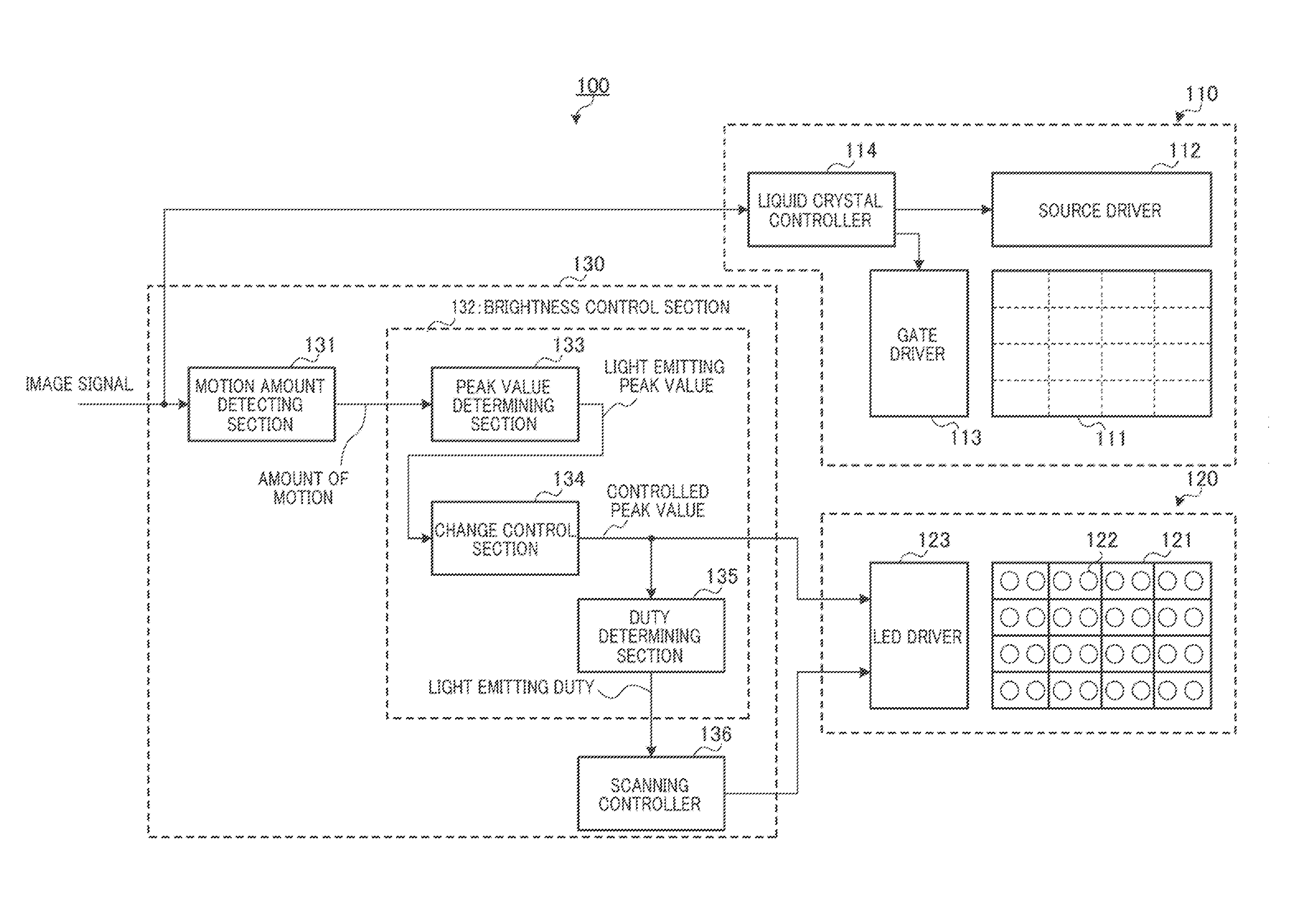
[0038]A configuration of a liquid crystal display apparatus will be described first. FIG. 4 is a block diagram showing a configuration of a liquid crystal display apparatus according to the embodiment. Liquid crystal display apparatus 100 shown in FIG. 4 has liquid crystal panel section 110, illuminating section 120, and drive control section 130. A configuration of illuminating section 120 and drive control section 130 configures a backlight apparatus.

[0039]Configurations of the sections will be described below in detail.

[0040]

[...

embodiment 2

[0099]Embodiment 2 of the present invention will be described below. A liquid crystal display apparatus according to the embodiment has the same basic configuration as that of the liquid crystal display apparatus according to the embodiment described above. Therefore, the same reference numerals as in the above embodiment denote the same or corresponding constituent elements in Embodiment 2, and a description thereof will be omitted. Different points between Embodiment 2 and the embodiment described above will be mainly described below.

[0100]In the embodiment, a case in which a change in peak value and an updating cycle are suppressed in a combination of backlight scanning and local dimming to prevent flicker upon change of driving waveforms will be described. In this case, the local dimming is a technique that controls a brightness for each light emitting area in accordance with an image to improve a contrast.

[0101]

[0102]FIG. 16 is a block diagram showing a configuration of a liqui...


PUM


Abstract

Provided is a backlight device wherein when the drive duty and the drive current are controlled according to a motion, the image quality is improved by preventing flicker caused by the change of the drive waveform. A light-emitting unit (121) comprises a plurality of light-emitting areas. A motion amount detecting unit (131) detects the motion amount of an image in each of a plurality of motion areas each corresponding to at least one or more light-emitting areas. A drive condition specifying unit specifies a drive condition including the duty and pulse height value of a drive pulse for causing each of the plurality of light-emitting areas to emit light, on the basis of the detected motion amount. A drive unit drives each of the plurality of light-emitting areas according to the specified drive condition. The drive condition specifying unit adjusts the drive condition such that the drive condition temporally smoothly changes.

Description

TECHNICAL FIELD [0001]The present invention relates a backlight apparatus and a display apparatus using the backlight apparatus.BACKGROUND ART [0002]A non-self-luminous display apparatus typified by a liquid-crystal display apparatus has a backlight apparatus (to be also simply referred to as a “backlight” hereinafter) on a backside thereof. The display apparatus displays an image through a light modulating section that adjusts an amount of reflection or an amount of transmission of light radiated from the backlight depending on an image signal. In the display apparatus, in order to reduce blurring of a moving image appearing in a hold type driving display apparatus, a light source is intermittently lighted in synchronism with scanning of an image.[0003]In general, in order to perform the intermittent lighting, a scheme that causes an entire light emitting area of the backlight to light at a predetermined timing (to be generally referred to as “backlight blink”) and a scheme that ve...

Claims


Application Information

Patent Timeline
IPC IPC(8): G09G5/10
CPCG09G3/3426G09G2320/0261G09G2320/0633H04N5/66G09G2320/0653G09G2320/106G09G2320/064
Inventor ONISHI, TOSHIKINAKANISHI, HIDEYUKIKOBAYASHI, TAKAHIROUMEDA, YOSHIOYAMAMURA, AKIHIROHAMADA, SEIJI
Owner PANASONIC CORP
Why Eureka
Try Eureka