Developer supply container and developer supplying system

a technology of developer supply and supply container, which is applied in the direction of electrographic process equipment, instruments, optics, etc., can solve the problems of developer not being able to easily discharge from the developer supply container, the flowability of the developer in the developer supply container is reduced, and the load in operation imparted to the user is reduced

Active Publication Date: 2012-01-19
CANON KK
View PDF3 Cites 65 Cited by
  • Summary
  • Abstract
  • Description
  • Claims
  • Application Information

AI Technical Summary

Benefits of technology

[0012]It is another object of the present invention to provide a developer supply container and a developer supplying system in which the developer in a developer supply container can be loosened properly by a suction operation through a discharge opening of the developer supply container by a pump portion
[0013]It is a furthe

Problems solved by technology

Thus, in the device disclosed in Japanese Laid-open Patent Application 2002-72649, the developer is automatically discharged, and therefore, the load in operation imparted to the user is reduced, but the following problems may arise.
Therefore, the

Method used


Image

  • Developer supply container and developer supplying system
  • Developer supply container and developer supplying system
  • Developer supply container and developer supplying system

Examples


embodiment 1

[0090]First, basic structures of an image forming apparatus will be described, and then, a developer replenishing apparatus and a developer supply container constituting a developer supplying system used in the image forming apparatus will be described.

(Image Forming Apparatus)

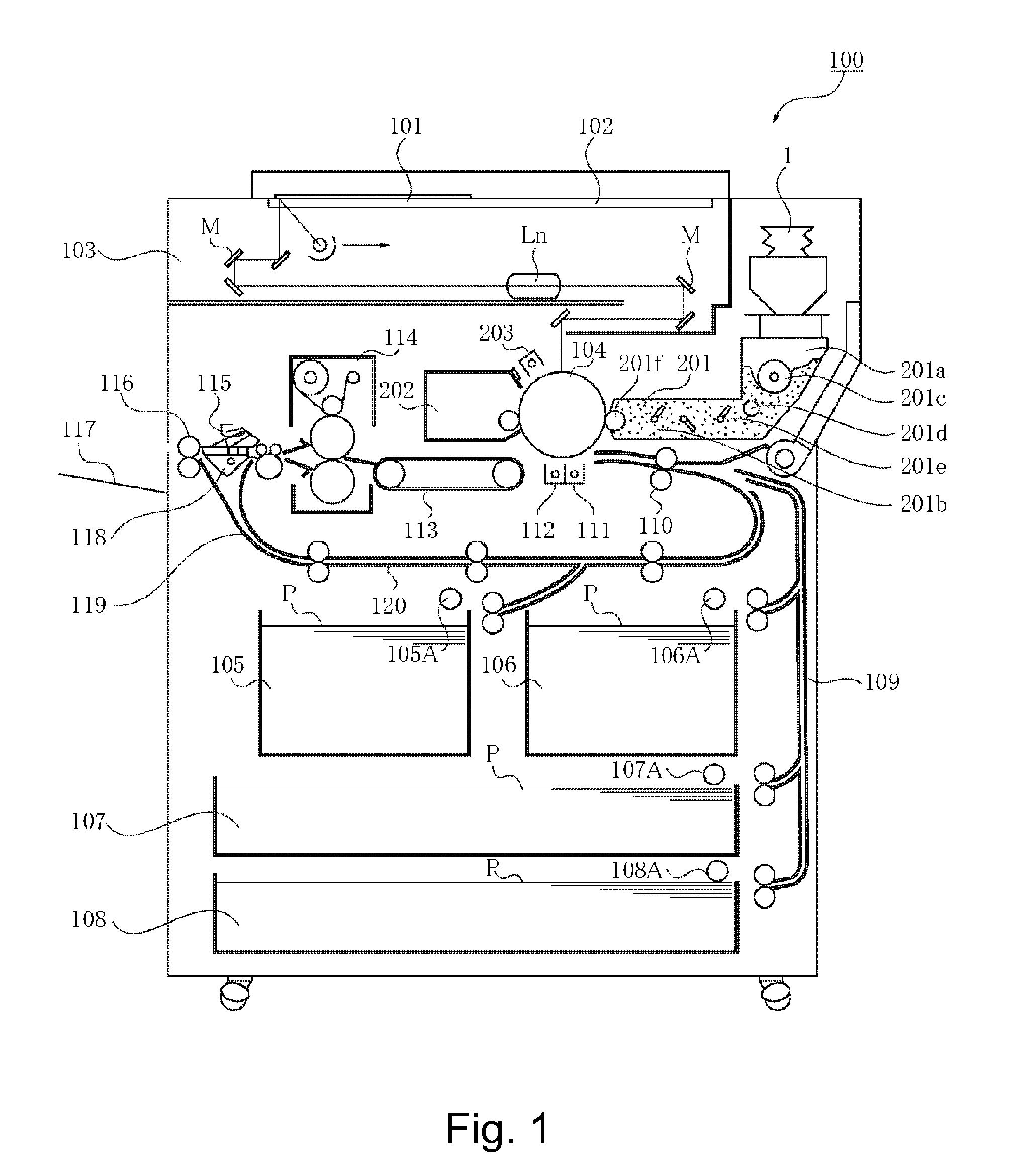
[0091]Referring to FIG. 1, the description will be made as to structures of a copying machine (electrophotographic image forming apparatus) employing an electrophotographic type process as an example of an image forming apparatus using a developer replenishing apparatus to which a developer supply container (so-called toner cartridge) is detachably mountable.

[0092]In the Figure, designated by 100 is a main assembly of the copying machine (main assembly of the image forming apparatus or main assembly of the apparatus). Designated by 101 is an original which is placed on an original supporting platen glass 102. A light image corresponding to image information of the original is imaged on an electrophotographic p...

embodiment 2

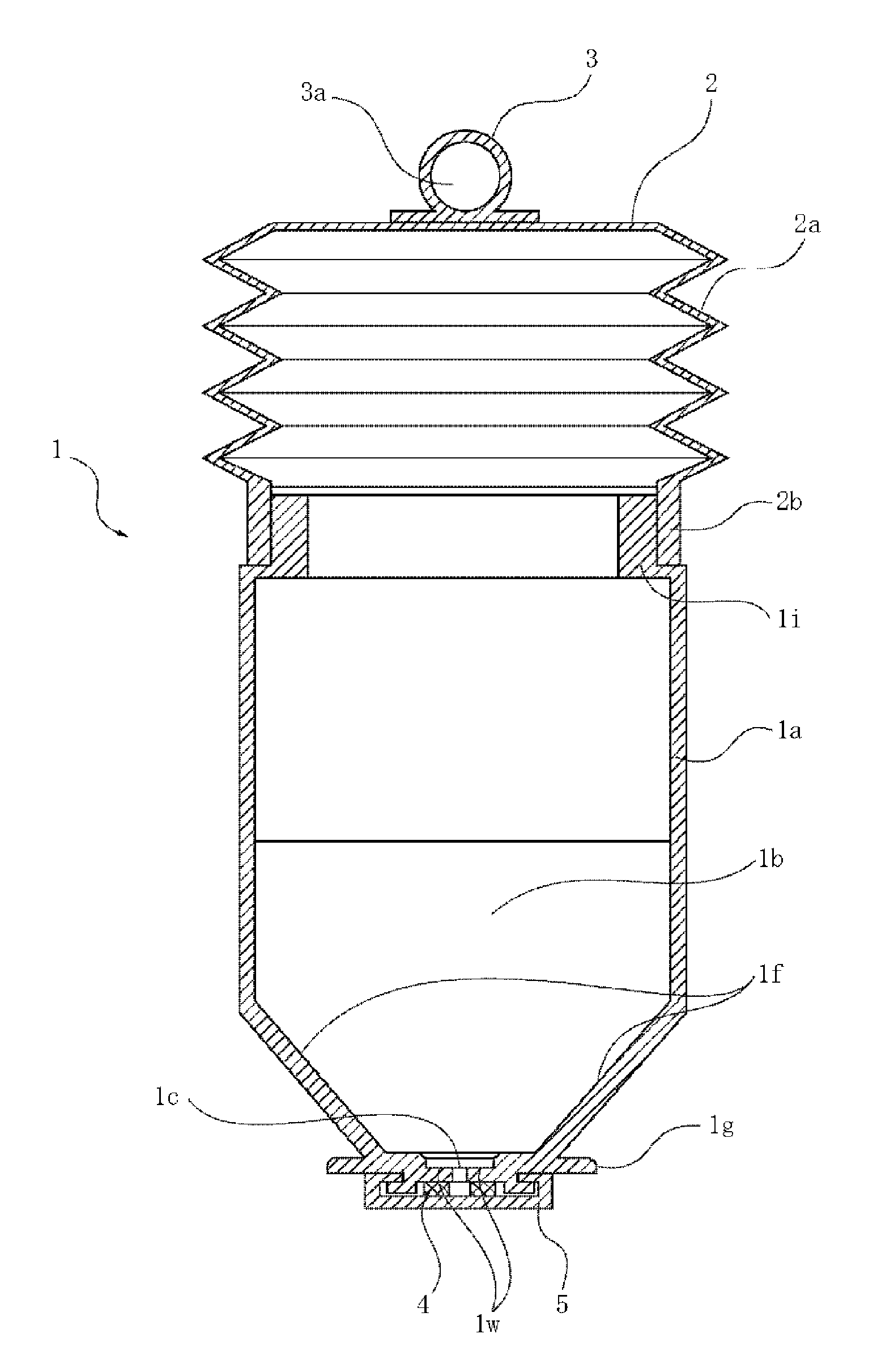
[0244]Referring to FIGS. 22, 23, a structure of the Embodiment 2 will be described. FIG. 22 is a schematic perspective view of a developer supply container 1, and FIG. 23 is a schematic sectional view of the developer supply container 1. In this example, the structure of the pump is different from that of Embodiment 1, and the other structures are substantially the same as with Embodiment 1. In the description of this embodiment, the same reference numerals as in Embodiment 1 are assigned to the elements having the corresponding functions in this embodiment, and the detailed description thereof is omitted.

[0245]In this example, as shown in FIGS. 22, 23, a plunger type pump is used in place of the bellow-like displacement type pump as in Embodiment 1. The plunger type pump includes an inner cylindrical portion 1h and an outer cylindrical portion 6 extending outside the outer surface of the inner cylindrical portion 1h and movable relative to the inner cylindrical portion 1h. The uppe...

embodiment 3

[0252]Referring to FIGS. 24, 25, a structure of Embodiment 3 will be described. FIG. 24 is a perspective view of an outer appearance in which a pump 12 of a developer supply container 1 according to this embodiment is in an expanded state, and FIG. 25 is a perspective view of an outer appearance in which the pump 12 of the developer supply container 1 is in a contracted state. In this example, the structure of the pump is different from that of Embodiment 1, and the other structures are substantially the same as with Embodiment 1. In the description of this embodiment, the same reference numerals as in Embodiment 1 are assigned to the elements having the corresponding functions in this embodiment, and the detailed description thereof is omitted.

[0253]In this example, as shown in FIGS. 24, 25, in place of a bellow-like pump having folded portions of Embodiment 1, a film-like pump 12 capable of expansion and contraction not having a folded portion is used. The film-like portion of the...


PUM


Abstract

Conventionally, the developer in the developer supply container is discharged by an air-supply pump and a suction pump which are provided in the main assembly side of the image forming apparatus, and therefore, the developer is compacted by the increase of the internal pressure of the developer supply container resulting from the air-supply. Therefore, the proper suction of the developer from the developer supply container becomes difficult with the result of shortage of the developer amount to be supplied.
A bellow-like pump is provided on the side of the developer supply container, and the pump alternately repeats the suction operation and the discharging operation through the discharge opening by a driving force inputted from the image forming apparatus side. By this, the developer can be sufficiently loosened, thus properly discharging the developer.

Description

FIELD OF THE INVENTION[0001]The present invention relates to a developer supply container detachably mountable to a developer replenishing apparatus and to a developer supplying system including them. The developer supply container and the developer supplying system are used with an image forming apparatus such as a copying machine, a facsimile machine, a printer or a complex machine having functions of a plurality of such machines.BACKGROUND ART[0002]Conventionally, an image forming apparatus of an electrophotographic type such as an electrophotographic copying machine uses a developer of fine particles. In such an image forming apparatus, the developer is supplied from the developer supply container in response to consumption thereof resulting from image forming operation.[0003]As for the conventional developer supply container, an example is disclosed in Japanese Laid-Open Utility Model Application Sho 63-6464.[0004]In the apparatus disclosed in Japanese Laid-Open Utility Model A...

Claims


Application Information

Patent Timeline
IPC IPC(8): G03G15/08
CPCG03G15/0877G03G15/0808G03G15/0849G03G15/0887G03G15/08G03G15/0856G03G15/0865G03G2215/0802G03G15/0867
Inventor OKINO, AYATOMONAGASHIMA, TOSHIAKIMURAKAMI, KATSUYATAZAWA, FUMIOYAMADA, YUSUKE
Owner CANON KK
Why Eureka
Try Eureka