Release mechanism for downhole tool

a technology of release mechanism and downhole tool, which is applied in the direction of drilling casings, drilling pipes, borehole/well accessories, etc., can solve the problems of premature failure and increased stress levels

Active Publication Date: 2008-09-23
BAKER HUGHES INC
View PDF28 Cites 99 Cited by
  • Summary
  • Abstract
  • Description
  • Claims
  • Application Information

AI Technical Summary

Problems solved by technology

Some of the problems with these designs lead to premature failure of the locking device creating a problem downhole.
If the tool is a disconnect, for example, it may release prematurely forcing a fishing operation to retrieve the lowermost portion that falls in the wellbore.
One of the reasons for the premature failure of the shear pins is the weight of the piston that has to ultimately move to break the shear pin or release a collet.
Other limitations of prior designs is that the locking members that were used to hold the components fixed to each other provided only discrete areas of contact about the periphery of the components causing elevated stress levels due to the minimal contact areas and creating another weakness that has in the past lead to premature failure.

Method used


Image

  • Release mechanism for downhole tool
  • Release mechanism for downhole tool
  • Release mechanism for downhole tool

Examples


Embodiment Construction

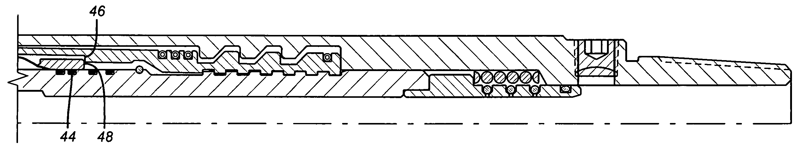
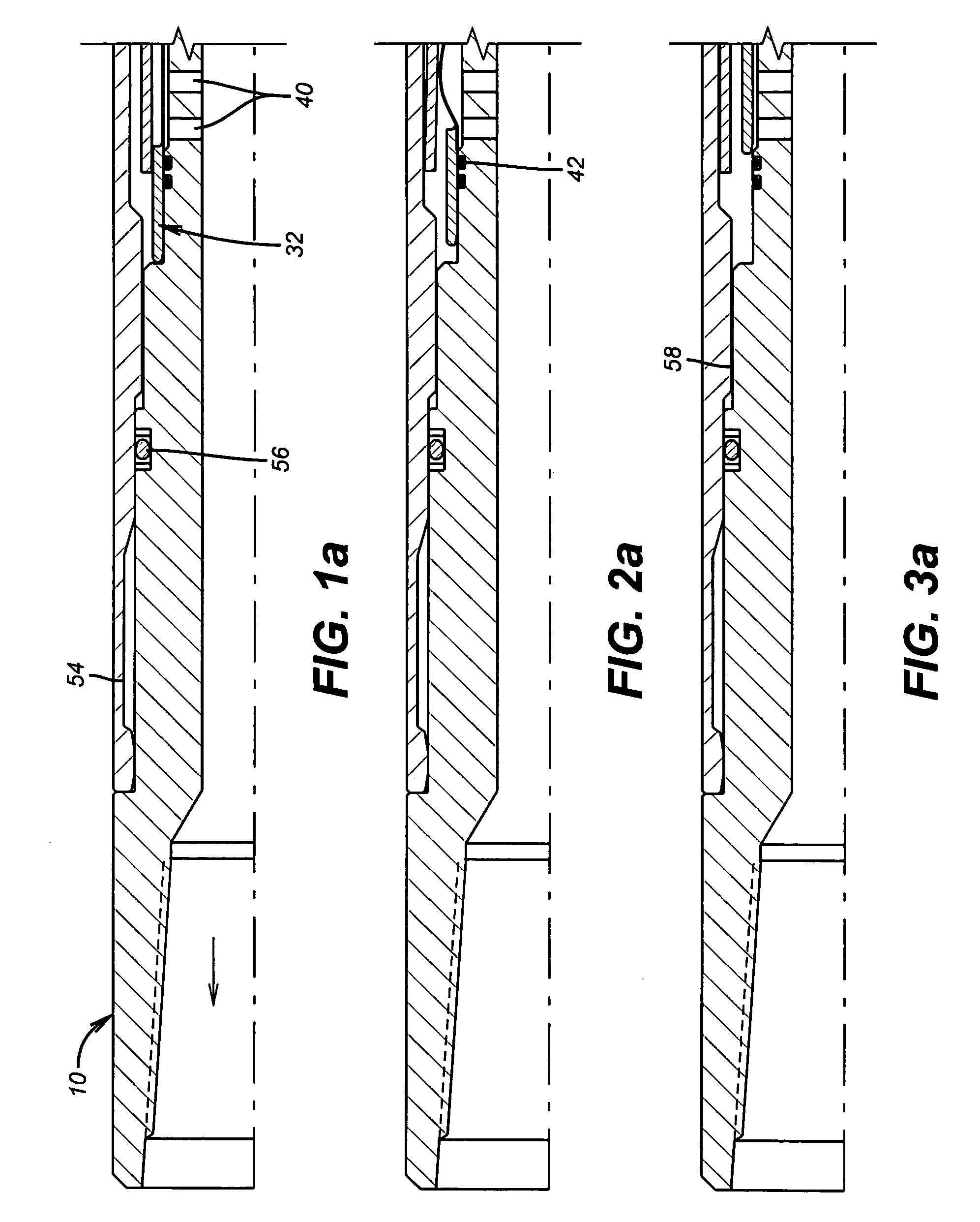
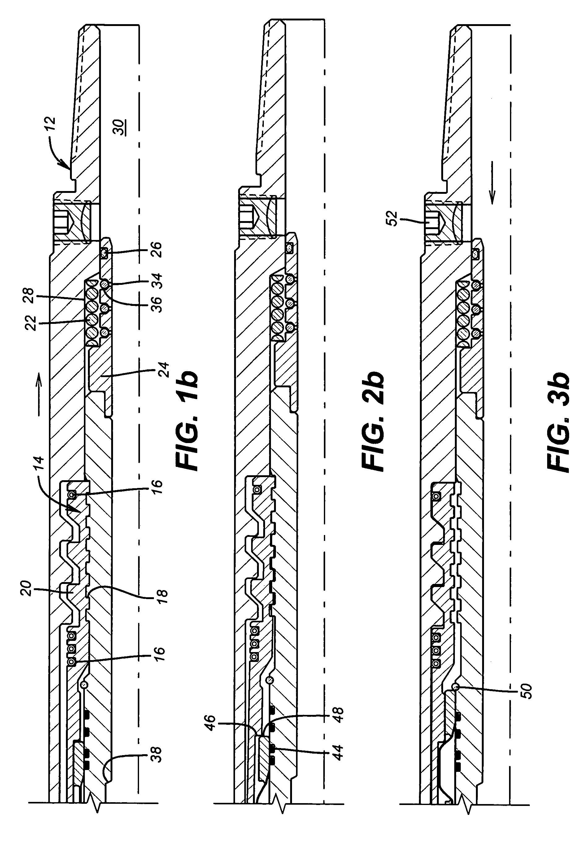
[0013]Referring to FIGS. 1a-1b, the upper body 10 is secured releaseably to lower body 12 through locking ring 14. Preferably, locking ring 14 is made of segments that are held against the upper body 10 by band springs 16 or other biasing member or members. The number and placement of the band springs 16 is variable with the application. In the preferred embodiment the band springs 16 straddle the first projection-depression mating profile 18 that is disposed between the upper body 10 and the locking ring 14. A second projection-depression mating profile 20 is disposed between the locking ring 14 and the lower body 12. Profiles 18 and 20 can take a variety of configurations. Those skilled in the art will appreciate that the greater the number of undulations the smaller the shear load on each undulation. Similarly, the greater the height from valley to peak the smaller the shear load on each undulation. To the extent the locking ring 14 is in segment, the segments can take the full c...


PUM


Abstract

A release mechanism for a downhole tool is actuated by radial movement of a locking member. The locking member provided as much as full circumferential support in the locked position and once released can be prevented from re-gripping the previously connected elements. Illustrative examples of the mechanism for radial movement for release comprise sleeves that expand and radially oriented pistons. Shear pins or collets are not used to hold the components together in the preferred embodiment. Internal pressure fluctuations before initiating the release sequence will not cause unwanted release. The mechanism is applicable to a variety of downhole tools and is illustrated in the context of a hydraulic release.

Description

FIELD OF THE INVENTION[0001]The field of this invention is a release device for downhole tools that relies on expansion or radial movement to effect release of components previously held together.BACKGROUND OF THE INVENTION[0002]Downhole tool frequently involve mechanisms to hold one portion of the tool to another. This is sometimes accomplished using shearable members such as shear pins or similar devices such as spring loaded collets. Typically pistons are used with such locking elements to respond to built up pressure after landing a ball on a seat and adding pressure from above. Some of the problems with these designs lead to premature failure of the locking device creating a problem downhole. If the tool is a disconnect, for example, it may release prematurely forcing a fishing operation to retrieve the lowermost portion that falls in the wellbore. One of the reasons for the premature failure of the shear pins is the weight of the piston that has to ultimately move to break the...

Claims


Application Information

Patent Timeline
Patent Type & Authority Patents(United States)
IPC IPC(8): E21B23/03
CPCE21B17/06
Inventor LYNDE, GERALD D.TOLLEFSBOL, TRACEY E.WILSON, III, STEVE B.
Owner BAKER HUGHES INC
Why Eureka
Try Eureka