Retracting containment arrow rest

a technology of containment arrows and rests, which is applied in the direction of spring guns, compressed gas guns, white arms/cold weapons, etc., can solve the problems of arrow rests not being able to move away from the arrow fast enough to allow the fletching, arrow rests may not be able to rebound into the path of the arrow, and archers may be injured

Inactive Publication Date: 2011-03-29
ATHENS OUTDOORS LLC
View PDF82 Cites 25 Cited by
  • Summary
  • Abstract
  • Description
  • Claims
  • Application Information

AI Technical Summary

Benefits of technology

[0013]Another principle object and advantage of the present invention is to enable the archer to shoot the bow from a vertical 90 degree, horizontal minus 90 degree or horizontal plus 90 degree position, the horizontal positions being achieved with the self centering radial motion of the support fingers moving in simultaneously to support the entire shaft's radius.
[0014]Another principle object and advantage of the present invention is that the self centering radial moving support fingers are actuated using the linear motion of the bow string or cable connected to the rest with the use of a rope, string, elastic string, cable, or rigid arm that will not slip and is tied or anchored to the string or cable with a knot, clamp, wrap or weaved method to ensure no slipping can occur once mounted to the string or cable.
[0015]Another principle object and advantage of the present invention is that the support fingers surround the arrow shaft 120 degrees apart with all support fingers moving in a self centering radial linear motion. This motion lifts the arrow and captures the arrow fully to ensure a straight line from the knock point to the center of the arrow rest. Once the arrow is released, the connection device or string moves back towards the actuator or pull arm to release the rest to the relaxed position. This motion releases the support fingers simultaneously in a complete radial linear motion to allow the arrow's shaft, vanes, or fletching to pass thru the rest without contact.
[0016]Another object and advantage of the present invention is that the arrow rest incorporates vertical up and down, horizontal left and right, forward, and backward adjustment mounts that mount the rest to the bow riser with the use of fasteners.
[0017]Another object and advantage of the present invention is that it also has fine adjustment mechanisms to limit the open diameter and closed diameter to accommodate different diameter arrow shafts.
[0018]Another object and advantage of the present invention is that the actuator arm has the ability to be loosened to adjust the rotation of the arm, thus adjusting the timing of the string or cable to the rest movement.

Problems solved by technology

Three of the problems that the current designs face are: the ability to contain the arrow to enable the archer to shoot at numerous angles; to be actuated fast enough to clear the arrow's vanes and fletching once the arrow is released; and third, once the rest drops out of the way it can bounce back into the flight path of the arrow when the archer releases the arrow due to recoil and or spring back in the apparatus itself.
First, most of the current drop-away arrow rests do not fully contain the arrow, but only support the arrow against the force of gravity. Thus, if the archer needs to move the bow to a position other than vertical, the arrow may drop off the rest, causing potential injury to the archer if the arrow is inadvertently released.
Second, many of the current rests do not actively release from the arrow, but depend on the force of gravity to allow the rest to passively drop away from the arrow upon firing. These rests may not be able to move away from the arrow fast enough to allow the fletching to clear the arrow rest.
Third, many of the current arrow rests require other accessories, such as a cable guard, for operation and cannot be used without these additional accessories. An example is the arrow rest described in U.S. Pat. No. 6,044,832.
Fourth, some of the rests bias the arrow support toward the arrow, depending on the relative movement of the bow limb, cable or string upon release to jerk the arrow support out of the path of the arrow, and then depend upon the restoring force of the spring to return the arrow support to a position where an arrow can again be loaded. An example is the arrow rest described in U.S. Pat. No. 4,803,971. Such arrow rests are unnecessarily complex and may cause the arrow rest to rebound into the path of the arrow.

Method used


Image

  • Retracting containment arrow rest
  • Retracting containment arrow rest
  • Retracting containment arrow rest

Examples


Embodiment Construction

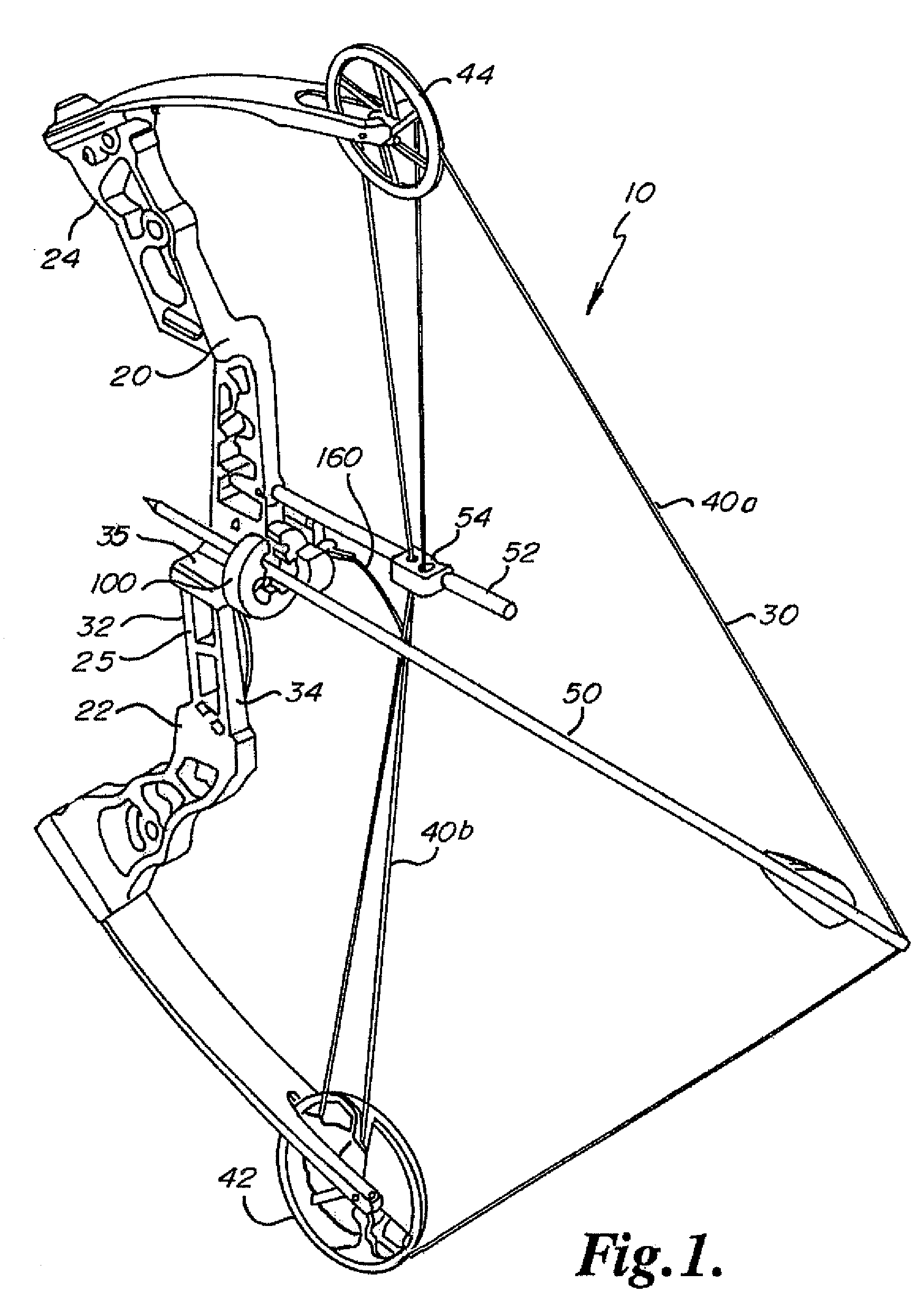
[0034]FIG. 1 illustrates an archery bow with the arrow rest 10 of the present invention attached thereto.

[0035]A compound bow 10 has a riser or frame 20 and a bow string 30. The riser 20 includes a lower portion 22 with a limb, an upper portion 24 with a limb, and a handle portion 25 with a grip (not shown) connected to and supporting the lower portion 22 and the upper portion 24. The handle portion 25 has a front surface 32 and an opposite real surface 34. During shooting with the bow, the front surface 32 is positioned facing the target and the back surface 34 is facing the archer. A ledge or shelf 35 is present above the handle portion 25.

[0036]The compound bow 10 has a pulley or cam 42 at the end of the lower portion 22 and a pulley or cam 44 at the end of the upper portion 24. The bowstring 30 extends between the cam 42 and the cam 44. The cams 42, 44 provide a mechanical advantage to the archer when drawing the bowstring 30.

[0037]The bowstring 30 includes at least two sections...


PUM


Abstract

An arrow rest that contains the arrow shaft before, during, and after the shot. To give the archer a precise, accurate shot, pull-away support fingers 120 degrees apart move in a self centering radial motion towards the center of the arrow shaft when the archer draws the bow to full draw and simultaneously pull away from the arrow shaft in a simultaneous radial motion to give complete clearance to the arrow shaft and its vanes or fletching once released from full draw.

Description

CROSS-REFERENCE TO RELATED APPLICATION[0001]The present application is based on and claims the benefit of U.S. provisional patent application Ser. No. 61 / 022,543, filed Jan. 22, 2008, the content of which is hereby incorporated by reference in its entirety.FIELD OF THE INVENTION[0002]This invention is an accessory for an arrow to rest in with an archery bow that is held vertically or horizontally. The rest has radial self centering moving support fingers that move in together and support the arrow shaft in a complete 360 degrees circumference. The support fingers move in simultaneously when the bow is drawn to completely support the shaft's diameter. The rest rapidly pulls away from the arrow when the arrow is released so that the fletching does not contact the rest. Once the arrow is loaded it cannot fall out the bottom, left, or night sides. Once the bow is drawn back, the arrow is fully contained or confined within the rest because the support fingers completely contact the arrow...

Claims


Application Information

Patent Timeline
Patent Type & Authority Patents(United States)
IPC IPC(8): F41B5/22
CPCF41B5/143
Inventor HUDKINS, JASON M.
Owner ATHENS OUTDOORS LLC
Why Eureka
Try Eureka