
Monitoring and control of power converters

a technology of power converters and monitoring and control, which is applied in the direction of power conversion systems, dc-dc conversion, instruments, etc., can solve the problems of affecting the load performance, transient power events may occur, and the voltage regulator may not be able to suitably track the speed of chang

Inactive Publication Date: 2009-12-17
UNIV OF COLORADO THE REGENTS OF
View PDF0 Cites 37 Cited by
  • Summary
  • Abstract
  • Description
  • Claims
  • Application Information

AI Technical Summary

Benefits of technology

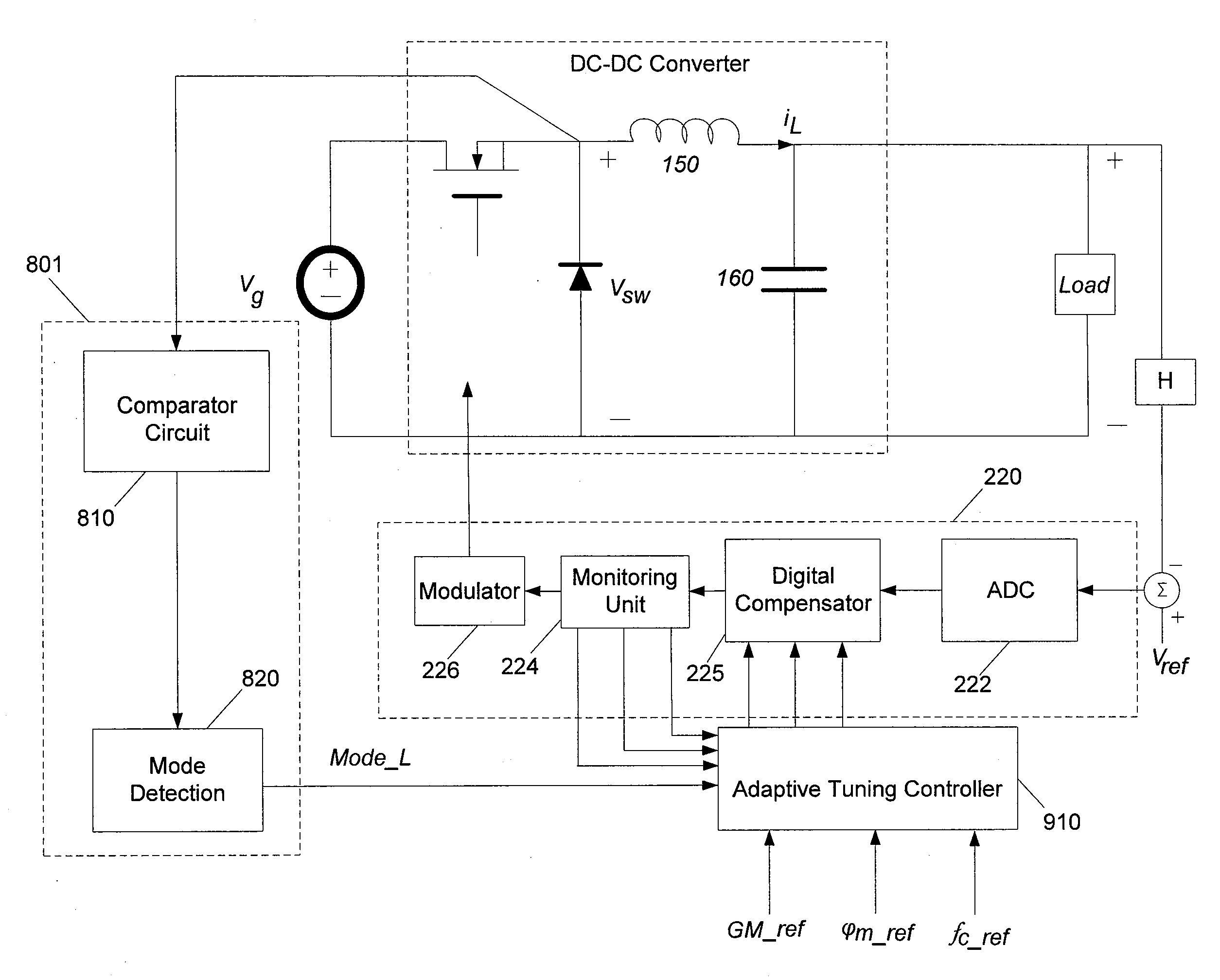
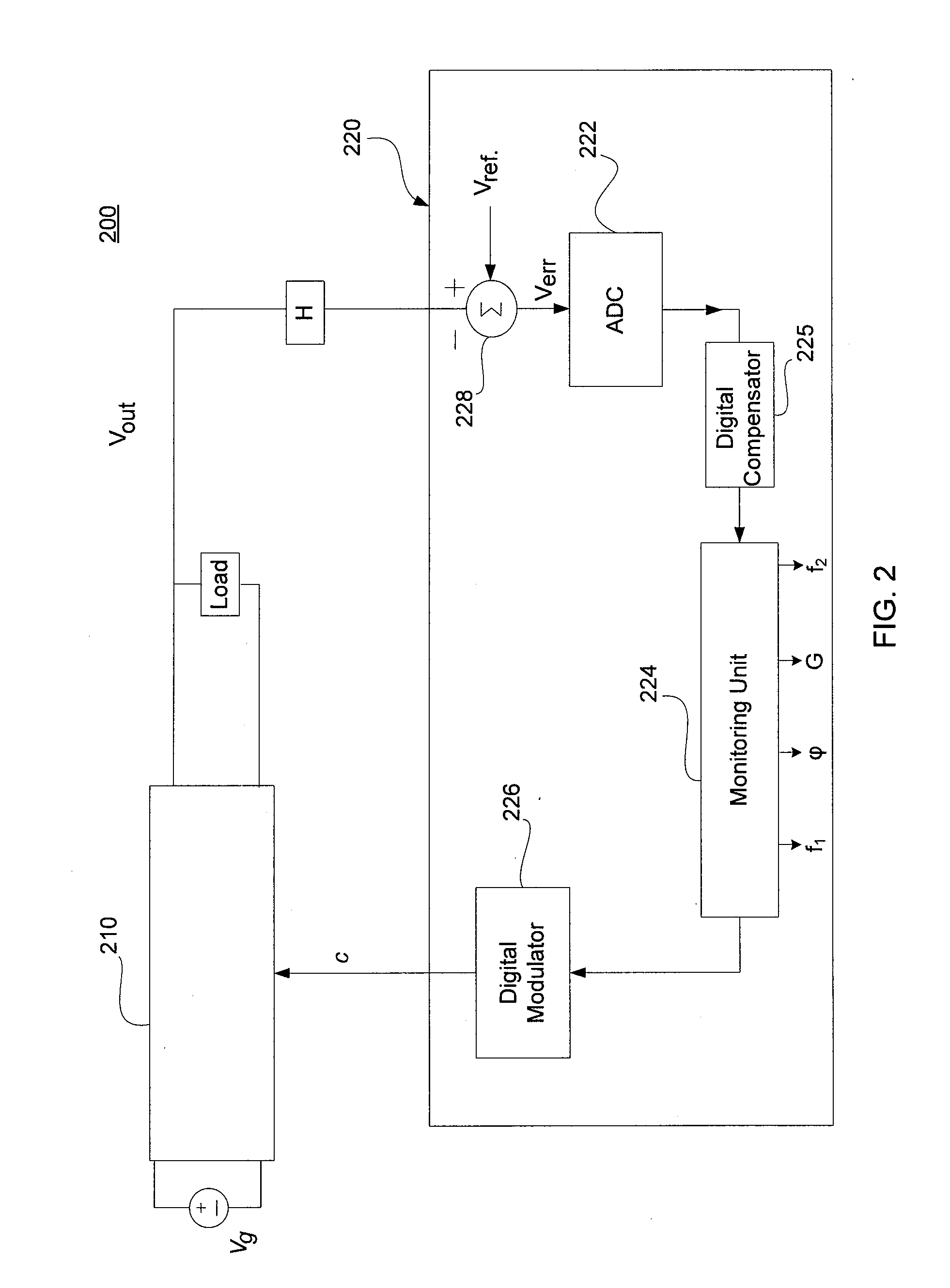
[0009]In accordance with an exemplary embodiment, a digital controller includes a comparator, an analog-to-digital converter (ADC), a digital compensator, a monitoring unit, and a digital modulator. The comparator receives an output signal from a power converter, and generates an error signal based at least in part on the difference between the feedback signal and a reference signal. The ADC converts the error signal into a digital form. The digital compensator processes the digital error signal and generates a control signal. Furthermore, the monitoring unit monitors at least one of phase, gain, and frequency of the power converter, and generates a digital feedback signal based on the control signal and an injected signal. The digital modulator receives the digital feedback signal from the monitoring unit, and transmits a control signal to the power converter to adjust the timing of the power converter.

Problems solved by technology

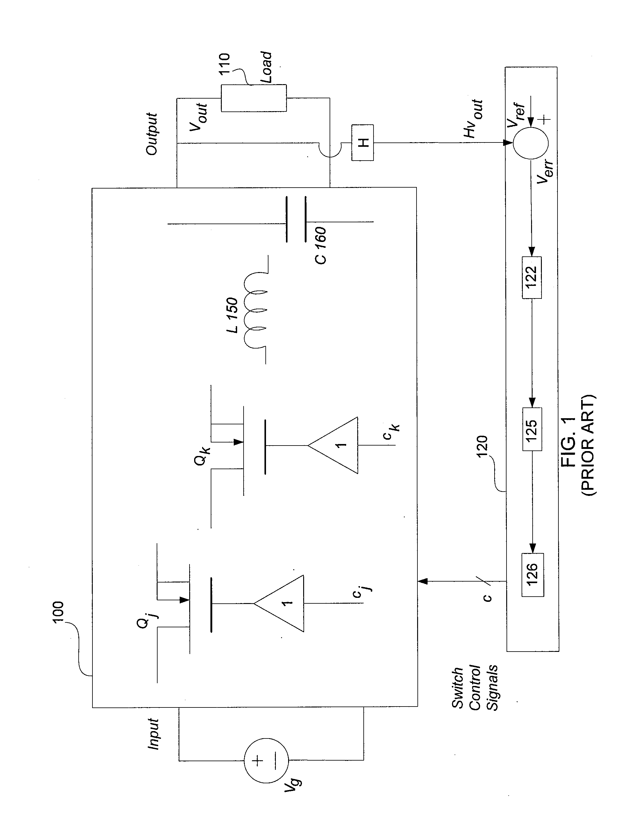
Typical prior art voltage regulators (e.g., a switching regulator) may be effective in tracking the slow power changes in the dynamic load; however, the voltage regulators may not be able to suitably track fast changes.
During operation of a dynamic load, transient power events may occur.
If adjustments to such transient events are not rapidly made, the load may experience drops or spikes in the voltage, which may in turn deleteriously affect the performance of the load.

Method used


Image

  • Monitoring and control of power converters
  • Monitoring and control of power converters
  • Monitoring and control of power converters

Examples


Embodiment Construction

[0026]While exemplary embodiments are described herein in sufficient detail to enable those skilled in the art to practice the invention, it should be understood that other embodiments may be realized and that logical electrical and system changes may be made without departing from the spirit and scope of the invention. Thus, the following detailed description is presented for purposes of illustration only.

[0027]The present invention relates to a power regulation system suitable for providing regulated power to, for example, a microelectronic device such as a microprocessor. In an exemplary embodiment, the regulated power signals include output voltage, output current, input voltage, input current, inductor current and capacitor voltage. In accordance with various exemplary embodiments of the present invention, the power regulation system and method of the present invention are configured to facilitate improved large-signal and small-signal dynamic responses of closed-loop power con...


PUM


Abstract

A digital controller configured to inject a signal into a digital feedback path that facilitates regulation of a power converter and measure the corresponding phase, gain, or frequency. The digital controller may also include an adaptive tuning controller for adjusting power converter operating attributes based in part on the measurements. In an exemplary embodiment, the adaptive tuning controller uses the phase, gain, and / or frequency measurements to adjust the digital feedback signal. In an exemplary embodiment, the adaptive tuning controller compares the operating measurements with desired values and generates adjusted operating attributes. In accordance with an exemplary embodiment, the monitoring and adjusting of the digital feedback signal occurs while the digital controller is regulating a power signal in the power converter.

Description

PRIORITY[0001]This application is a non-provisional of U.S. Provisional No. 61 / 152,373, filed on Feb. 13, 2009, and entitled “ROBUST ADAPTIVE TUNING OF DIGITALLY CONTROLLED SWITCHED-MODE POWER SUPPLIES” and further claims priority to U.S. Provisional No. 61 / 061,486, filed on Jun. 13, 2008, and entitled “METHOD, APPARATUS & SYSTEM FOR EXTENDED SWITCHED-MODE CONTROLLER”, both of which are hereby incorporated by reference.FIELD OF INVENTION[0002]The present invention relates generally to power converters and, in particular, to power regulation systems, devices, and methods suitable for monitoring and controlling closed-loop power converters.BACKGROUND OF THE INVENTION[0003]Power converters include direct current (“DC”)-DC, DC-alternating current (“AC”), AC-DC, and AC-AC configurations. DC-DC power converters are often used to provide regulated power to electrical loads in, for example, microelectronic devices. Typical power converter feedback loops are conservatively designed so that s...

Claims


Application Information

Patent Timeline
Patent Type & Authority Applications(United States)
IPC IPC(8): G05F1/10
CPCH02M3/157
Inventor MORRONI, JEFFREYMAKSIMOVIC, DRAGANZANE, REGAN
Owner UNIV OF COLORADO THE REGENTS OF
Learn More