Storage system and storage control method achieving both power saving and good performance

a technology of storage control and power saving, applied in the field of storage system and, can solve the problems that the art for realizing this cannot be elicited from document 1, document 2, or a combination, and achieve the effect of reducing the power consumption valu

Inactive Publication Date: 2007-12-20
HITACHI LTD
View PDF2 Cites 39 Cited by
  • Summary
  • Abstract
  • Description
  • Claims
  • Application Information

AI Technical Summary

Benefits of technology

[0014]In a first embodiment, the power consumption control comprises carrying out power consumption suppression control in which the power consumption value is suppressed but a load device operating state is degraded, and releasing the power consumption suppression control, so as to adjust the number of times that the power consumption suppression control is carried out. For example, in the case that the difference between the power consumption value and the allowed power value this time has become greater than the difference between the power consumption value and the allowed power value after the power consumption control last time, this difference can be reduced by stopping the power consumption suppression control being carried out. Moreover, in the case, for example, that the power consumption value this time exceeds the allowed power value, the power consumption value can be reduced by carrying out the power consumption suppression control.

Problems solved by technology

However, art for realizing this cannot be elicited from document 1, document 2, or a combination thereof.

Method used


Image

  • Storage system and storage control method achieving both power saving and good performance
  • Storage system and storage control method achieving both power saving and good performance
  • Storage system and storage control method achieving both power saving and good performance

Examples


Embodiment Construction

[0053]Following is a description of an embodiment of the present invention.

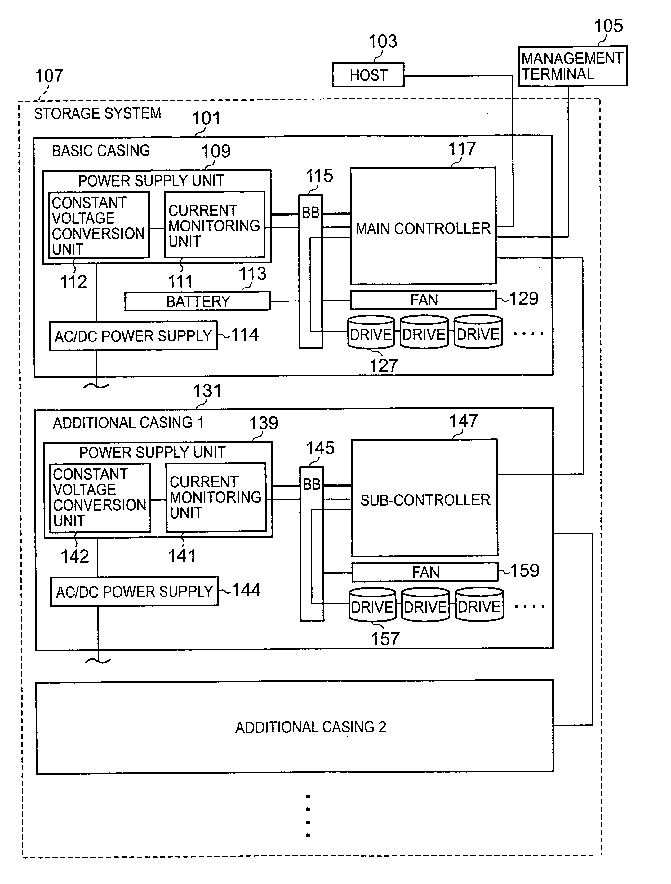
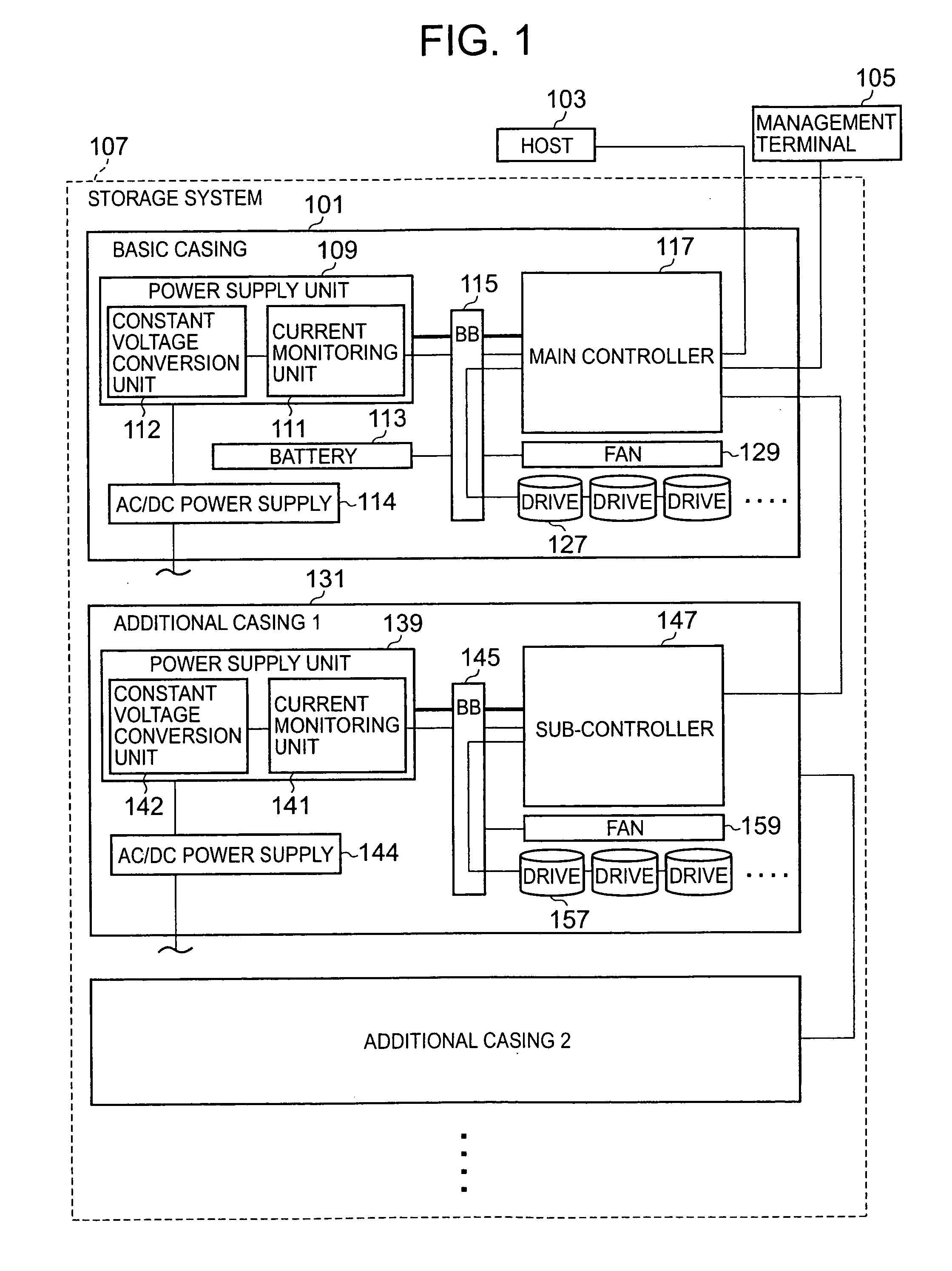
[0054]FIG. 1 is a diagram showing an example of the construction of a storage system according to an embodiment of the present invention.

[0055]The storage system 107 has connected thereto a host computer 103, which is a type of host device, and a computer (hereinafter “management terminal”) 105 for managing the storage system 107.

[0056]The host computer 103 issues IO (input / output) commands to the storage system 107. The IO commands are, for example, at least one of write commands for writing data to the storage system, and read commands for reading data from the storage system.

[0057]The management terminal 105 is able to set various information in the storage system 107, and receive and store various information from the storage system 107. The function of the management terminal 105 will be described in detail later.

[0058]The storage system 107 can be constructed from at least a basic casing 101 out of the ...


PUM


Abstract

A storage system connected to a host device from which IO commands are sent comprises a plurality of load devices that act as loads including a plurality of storage devices, a current measuring unit that measures a current value flowing into the plurality of load devices, a power calculating unit that calculates at each time a power consumption value consumed by the plurality of load devices based on the measured current value, and a controller that receives an IO command from the host device, and accesses a storage device that follows the IO command out of the plurality of storage devices. The controller carries out power consumption control such that the calculated power consumption value is not more than a predetermined allowed power value and a difference between the power consumption value and the allowed power value is as small as possible.

Description

CROSS-REFERENCE TO PRIOR APPLICATION[0001]This application relates to and claims priority from Japanese Patent Application No. 2006-170563, filed on Jun. 20, 2006, the entire disclosure of which is incorporated herein by reference.BACKGROUND OF THE INVENTION[0002]1. Field of the Invention[0003]The present invention relates to controlling the power consumption of a storage system having a plurality of storage devices therein.[0004]2. Background of the Invention[0005]In recent years, computerization has proceeded, and management of enormous amounts of data has come to be required. Accompanying this, there have been advances in increasing the capacity of storage systems.[0006]One method of increasing the capacity of a storage system is to increase the number of storage devices installed therein. Examples of storage devices are disk devices (e.g. hard disk drives). However, a large amount of power is consumed in rotating a disk, and hence upon increasing the number of disk devices, the ...

Claims


Application Information

Patent Timeline
Patent Type & Authority Applications(United States)
IPC IPC(8): G06F1/26
CPCG06F1/3221G06F1/3268G06F3/0625Y02B60/1246G06F3/0659G06F3/0689G06F3/0653Y02D10/00
Inventor KAKIHARA, SHINOBUSATO, MITSUHIDE
Owner HITACHI LTD
Why Eureka
Try Eureka