Combined brush seal and labyrinth seal segment for rotary machines

a technology of labyrinth seal and brush seal, which is applied in the direction of engine seal, machine/engine, stators, etc., can solve the problems of increasing wear and inability to accommodate radial excursions of shafts, and achieves general applicability to rotary machines, improved sealing, and increased turbine efficiency

Inactive Publication Date: 2002-08-20
GENERAL ELECTRIC CO
View PDF88 Cites 25 Cited by
  • Summary
  • Abstract
  • Description
  • Claims
  • Application Information

AI Technical Summary

Benefits of technology

In accordance with a preferred embodiment of the present invention, there is provided brush seal segments in the environment of a rotary machine such as a turbine. Brush seals per se have general applicability to rotary machines and can be used in lieu of labyrinth seals. Brush seals are advantageous in that context and provide improved sealing, while occupying considerably less axial space as compared with conventional labyrinth seals. As a result, more compact rotary machine, e.g., turbine, designs can be realized. Alternatively, by employing brush seals, the span that would normally be occupied by labyrinth teeth can be used to allow additional turbine stages, resulting in increased turbine efficiency. As a further advantage, application of brush seals at end packing locations can reduce leakage to the point that the need for a gland sealing / exhauster system, for example, in a steam turbine, is eliminated. At rotor end seals, it is also possible to use brush seals in conjunction with face seals. Further, in certain steam rotary machine applications, some leakage is desirable for cooling of components such as rotors. At these locations, brush seals can be used in conjunction with orifices or other flow bypass mechanisms to ensure that the proper amount of leakage is obtained.

Problems solved by technology

Further, in certain steam rotary machine applications, some leakage is desirable for cooling of components such as rotors.
This would result in increased wear and not accommodate radial excursions of the shaft.

Method used


Image

  • Combined brush seal and labyrinth seal segment for rotary machines
  • Combined brush seal and labyrinth seal segment for rotary machines
  • Combined brush seal and labyrinth seal segment for rotary machines

Examples


Embodiment Construction

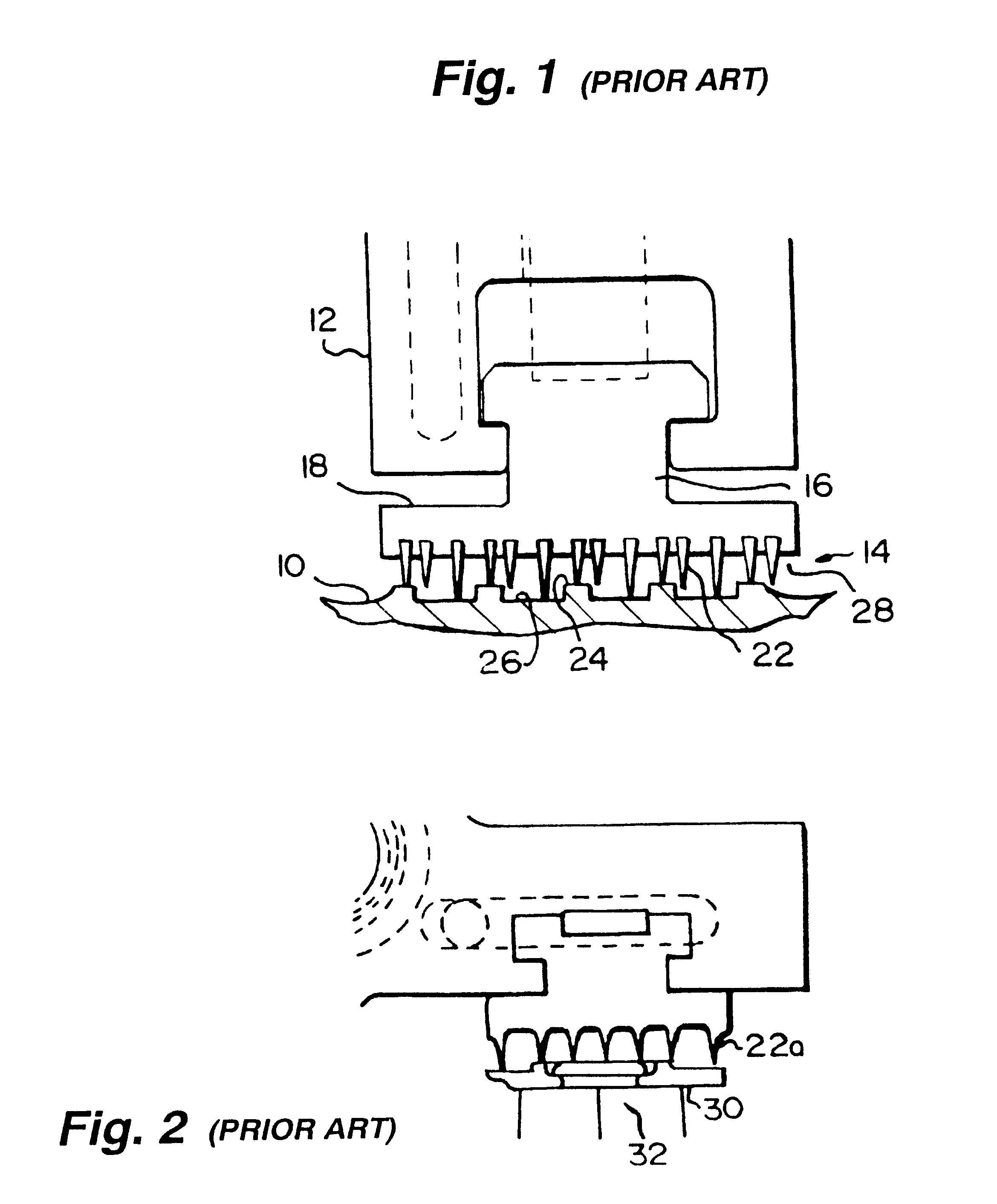
Referring now to the drawing figures, particularly to FIG. 1, there is illustrated a portion of a rotary machine, for example, a steam turbine, having a turbine shaft 10 disposed in a turbine housing 12 and which shaft 10 is supported by conventional means, not shown, within turbine housing 12. A labyrinth seal, generally designated 14, between the rotating shaft 10 and the stationary housing 12, includes a seal ring 16 disposed about shaft 10 separating high and low pressure regions on axially opposite sides of the ring. It will be appreciated that while only one seal 16 is disclosed, typically multiple-stage labyrinth seals are provided about rotor shafts. Each seal ring 16 is formed of an annular array of a plurality of arcuate seal elements 18 having sealing faces 20 and a plurality of radially projecting, axially spaced teeth 22. The teeth are of a hi-lo design for obtaining close clearances with the radial projections or ribs 24 and the grooves 26 of the shaft 10. The labyrint...


PUM


Abstract

A brush seal is comprised of arcuate seal segments having ends cut in a radial direction with bristles "canted" at an approximate 45.degree. angle relative to radii of the segments, leaving triangular regions adjacent one end of each segment devoid of bristles at the segment interfaces. The brush seals are retrofit into conventional labyrinth seals with the backing plate for the bristles comprising a labyrinth tooth profile extending fully 360.degree. about the seal, including those areas where bristles are not present. The sealing capacity is not substantially degraded, while affording significant sealing improvements over conventional labyrinth seals. Additionally, when retrofit into labyrinth seals with radial movement, the individual labyrinth seal segments are free to move radially independently of one another during transients.

Description

TECHNICAL FIELDThe present invention relates to brush seals for rotary machines such as steam and gas turbines and particularly relates to brush seals and labyrinth-brush seal combinations for use with rotary machines.BACKGROUNDRotary machines, such as steam and gas turbines, used for power generation and mechanical drive applications are generally large machines consisting of multiple turbine stages. In turbines, high pressure fluid flowing through the turbine stages must pass through a series of stationary and rotating components, and seals between the stationary and rotating components are used to control leakage. The efficiency of the turbine is directly dependent on the ability of the seals to prevent leakage, e.g., between the rotor and stator. Turbine designs are conventionally classified as either impulse, with the majority of the pressure drop occurring across fixed nozzles, or reaction, with the pressure drop more evenly distributed between the rotating and stationary vane...

Claims


Application Information

Patent Timeline
Patent Type & Authority Patents(United States)
IPC IPC(8): F01D11/08F01D11/00F01D9/02F01D11/12F01D11/02F16J15/44F16J15/32
Inventor SKINNER, DAVID ROBERTBAGEPALLI, BHARAT S.CROMER, ROBERT HAROLDDINC, OSMAN SAIMTURNQUIST, NORMAN ARNOLDWOLFE, CHRISTOPHER EDWARD
Owner GENERAL ELECTRIC CO
Why Eureka
Try Eureka