Exhaust Purification Apparatus

a technology purification chamber, which is applied in mechanical apparatus, machines/engines, separation processes, etc., can solve the problems of complex construction of exhaust purification apparatus, difficult introduction of exhaust, and difficulty in ensuring the mixing time of urea water, etc., and achieves the effect of small and simple construction, and simple construction

a technology purification chamber, which is applied in mechanical apparatus, machines/engines, separation processes, etc., can solve the problems of complex construction of exhaust purification apparatus, difficult introduction of exhaust, and difficulty in ensuring the mixing time of urea water, etc., and achieves the effect of small and simple construction, and simple construction

US20120023914A1Inactive Publication Date: 2012-02-02YANMAR POWER TECHNOLOGY CO LTD

Image

  • Exhaust Purification Apparatus
  • Exhaust Purification Apparatus
  • Exhaust Purification Apparatus

Examples


first embodiment

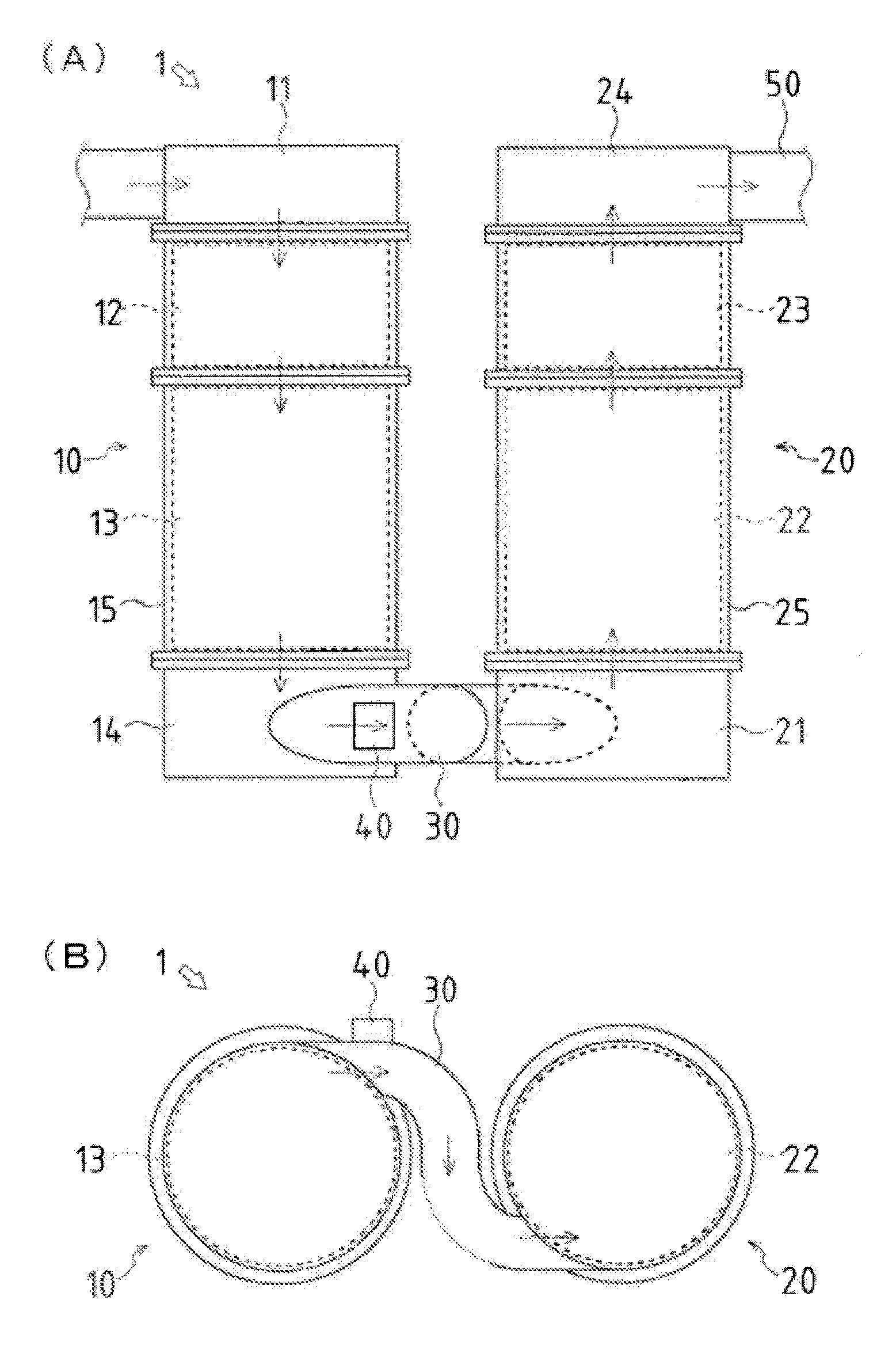
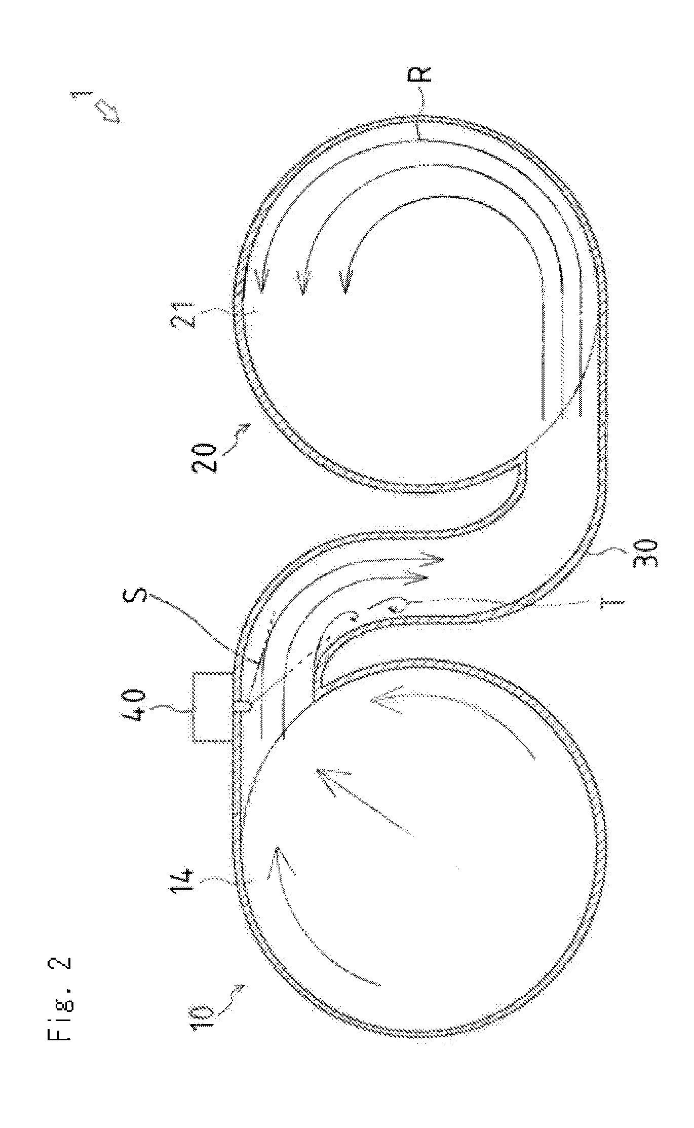
[0070]Similarly to the present invention, the upstream side of the communication pipe 30 is extended along the tangential direction of the first processing unit 10 while the axis of the communication pipe 30 at the connection part of the communication pipe 30 and the first processing unit 10 does not cross the axis of the first processing unit 10. The middle portion of the communication pipe 30 passes through the space between the first processing unit 10 and the second processing unit 20 at which the first processing unit 10 is the most close to the second processing unit 20. The downstream side of the communication pipe 30 is shifted to the position along the tangential direction of the second processing unit 20 while the axis of the communication pipe 30 does not cross the axis of the second processing unit 20, and is connected to the exhaust inlet provided in the inlet chamber 21 of the second processing unit 20.

[0071]In this case, the first processing unit 10 and the second pro...

second embodiment

[0073]Accordingly, in the second embodiment, the first processing unit 10 and the second processing unit 20 are arranged close to each other, whereby the exhaust purification apparatus 1 can be miniaturized further.

[0074]The exhaust gas to which the urea water S is supplied by the reducing agent supply unit 40 is contracted by the reduced diameter portion 30a and then expanded, whereby the evaporation and mixing of the urea water S can be promoted further. In the reduced diameter portion 30a positioned between the first processing unit 10 and the second processing unit 20, heat transmitted from the exhaust gas is hard to be dispersed so that respective high temperature can be maintained, whereby the evaporation of the urea water S can be promoted.

[0075]Furthermore, when the diesel engine is at low output driving state with small exhaust gas flow rate, the communication pipe 30 is provided so that the axis of the connection part of the communication pipe 30 and the first processing u...


PUM

PropertyMeasurementUnit
diameteraaaaaaaaaa
timeaaaaaaaaaa
soluble organic fractionaaaaaaaaaa

Abstract

Disclosed is an exhaust purification apparatus which comprises: a first processing unit (10) for removing particulate matter; a second processing unit (20) for mainly reducing nitrogen oxide from the exhaust that has passed through the first processing unit (10); a communication pipe (30) for guiding the exhaust from an exhaust outlet of the first processing unit (10) to an exhaust inlet of the second processing unit (20); and a reducing agent supply unit (40) for supplying a reducing agent to the exhaust. The first processing unit (10) and the second processing unit (20) are arranged in parallel to each other in such a manner that the exhaust outlet of the first processing unit (10) and the exhaust inlet of the second processing unit (20) are on the sides facing each other. The communication pipe (30) is arranged in a space between the first processing unit (10) and second processing unit (20) where the processing units are closest to each other in such a manner that the upstream part of the communication pipe (30) extends from the exhaust outlet of the first processing unit (10) along the outer circumferential surface of the first processing unit (10) and the downstream part of the communication pipe (30) extends along the outer circumferential surface of the second processing unit (20) to the exhaust inlet of the second processing unit (20). The reducing agent supply unit (40) is provided on the communication pipe (30).

Description

TECHNICAL FIELD[0001]The present invention relates to an art of an exhaust purification apparatus of a diesel engine.BACKGROUND ART[0002]Exhaust gas discharged from a diesel engine includes particle matter represented by soot and the like and nitrogen oxide represented by nitrogen monoxide and the like. As a means for removing the particle matter, a particle matter filter device which filters the exhaust gas with a filter carrier is known. As a means for removing the nitrogen oxide, a nitrogen oxide reductor is known as what reduces the nitrogen oxide with a reduction catalytic carrier after supplying urea water to the exhaust gas.[0003]In the case that the particle matter filter device and the nitrogen oxide reductor are employed as a exhaust purification apparatus so as to purify the exhaust gas discharged from the diesel engine, firstly, the particle matter in the exhaust gas is removed by the particle matter filter device, and then the nitrogen oxide is reduced by the nitrogen o...

Claims


Application Information

Patent Timeline
02 Feb 2012
Publication
US20120023914A1
IPC
F01N3/18
CPC
B01D53/9431; F01N2610/02; B01D53/9477; B01D2251/2067; B01D2257/404; B01D2258/012; F01N3/0821; F01N3/2066
Inventors
OMOTE, HIROSHI; OKADA, SHUSUKE