Exhaust purification apparatus

a technology purification chamber, which is applied in mechanical apparatus, machines/engines, separation processes, etc., can solve the problems of complex construction of exhaust purification apparatus, difficult introduction of exhaust, and difficulty in ensuring the mixing time of urea water, etc., and achieves the effect of small and simple construction, and simple construction

Inactive Publication Date: 2014-01-14
YANMAR POWER TECHNOLOGY CO LTD
View PDF17 Cites 0 Cited by
  • Summary
  • Abstract
  • Description
  • Claims
  • Application Information

AI Technical Summary

Benefits of technology

[0016]The present invention constructed as the above brings the following effects.
[0017]According to the first mode of the present invention, the exhaust purification apparatus can be constructed small and simple, and the mixing of the exhaust gas and the urea water supplied thereto can be promoted.
[0018]According to the second mode of the present invention, the exhaust purification apparatus can be constructed small and simple, and the mixing of the exhaust gas and the urea water supplied thereto can be promoted at the time of low output driving of the diesel engine.
[0019]According to the third mode of the present invention, the exhaust purification apparatus can be constructed small and simple, and the mixing of the exhaust gas and the urea water supplied thereto can be promoted. By a turning flow, exhaust gas can be introduced into the reduction catalytic carrier uniformly without any bias.
[0020]According to the fourth mode of the present invention, the exhaust purification apparatus can be constructed small and simple, and the mixing of the exhaust gas and the urea water supplied thereto can be promoted further. By the turning flow, exhaust gas can be introduced into the reduction catalytic carrier uniformly without any bias.
[0021]According to the fifth mode of the present invention, the exhaust purification apparatus can be constructed even smaller, and the mixing of the exhaust gas and the urea water supplied thereto can be promoted further. By the turning rotational flow, exhaust gas can be introduced into the reduction catalytic carrier uniformly without any bias.

Problems solved by technology

However, when the particle matter filter device and the nitrogen oxide reductor are arranged in parallel to each other, it is difficult to secure the mixing time from the supply of urea water to the exhaust gas until the urea water and the exhaust gas are mixed uniformly.
It is also difficult to introduce the exhaust gas including the urea water into the reduction catalytic carrier constituting the nitrogen oxide reductor uniformly without any bias.
Accordingly, a perforated plate or the like must be arranged in the exhaust path, whereby construction of an exhaust purification apparatus must be complex.
However, it is difficult to mix the suitable amount of urea water exhaust gas and introduce them into the nitrogen oxide reductor.Patent Literature 1: the Japanese Patent Laid Open Gazette 2005-155404Patent Literature 2: the Japanese Patent Laid Open Gazette 2008-138654

Method used


Image

  • Exhaust purification apparatus
  • Exhaust purification apparatus
  • Exhaust purification apparatus

Examples


first embodiment

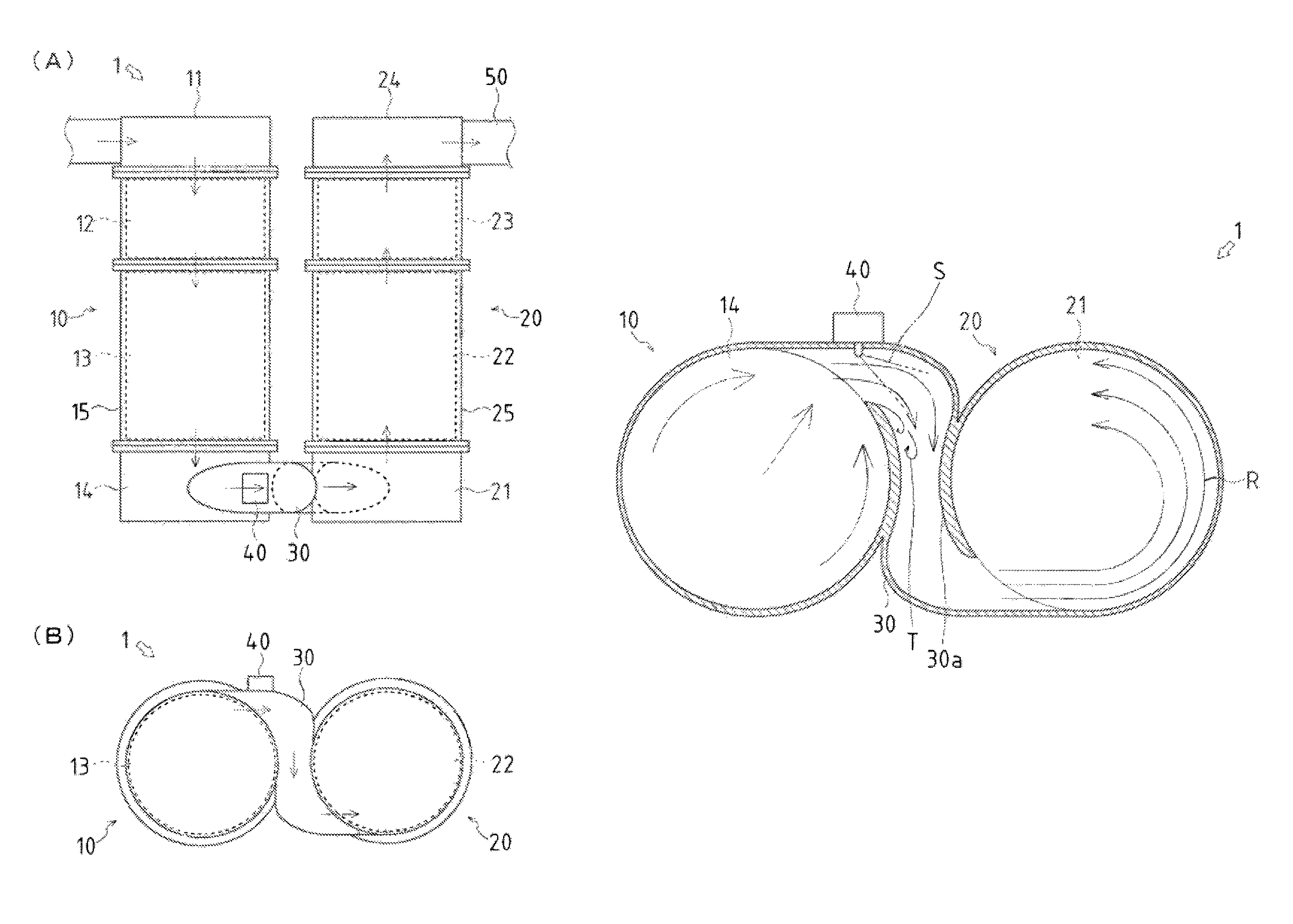
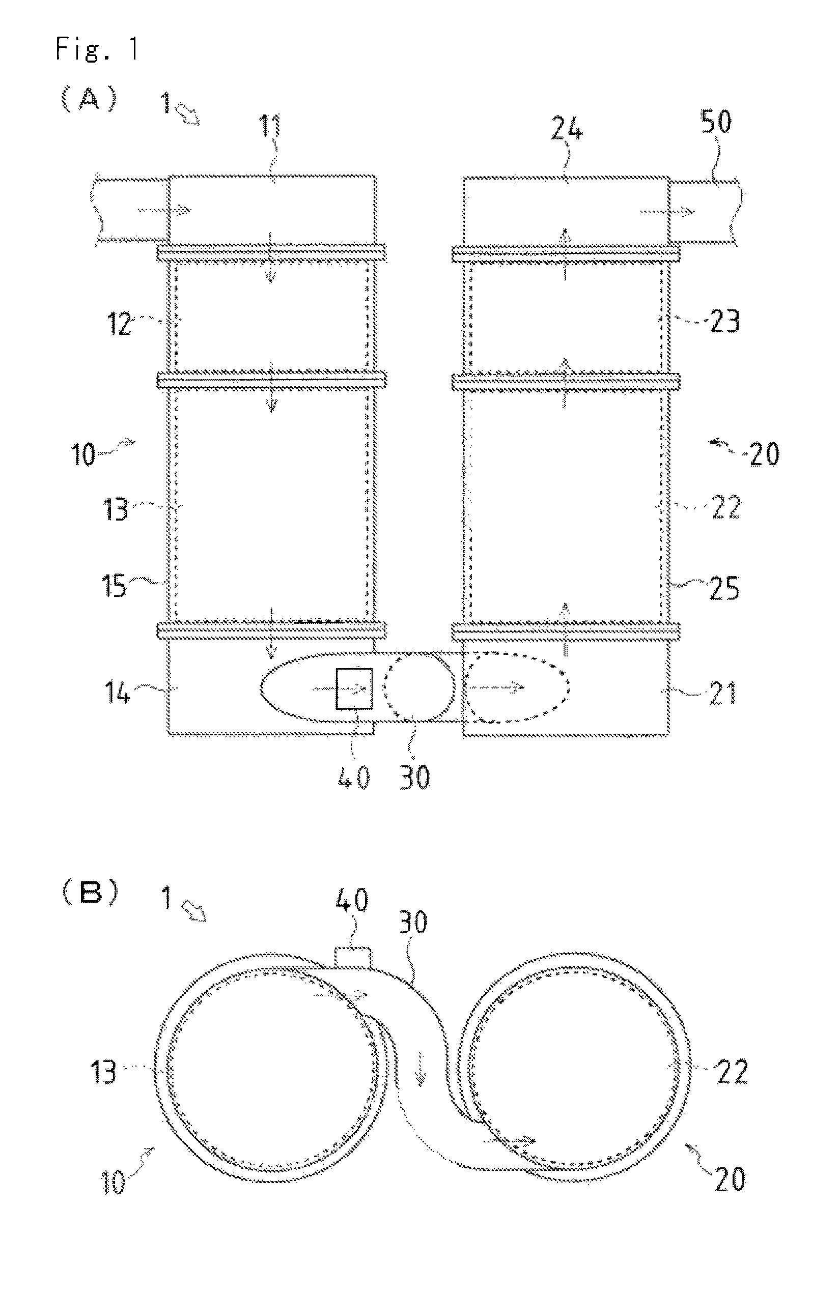
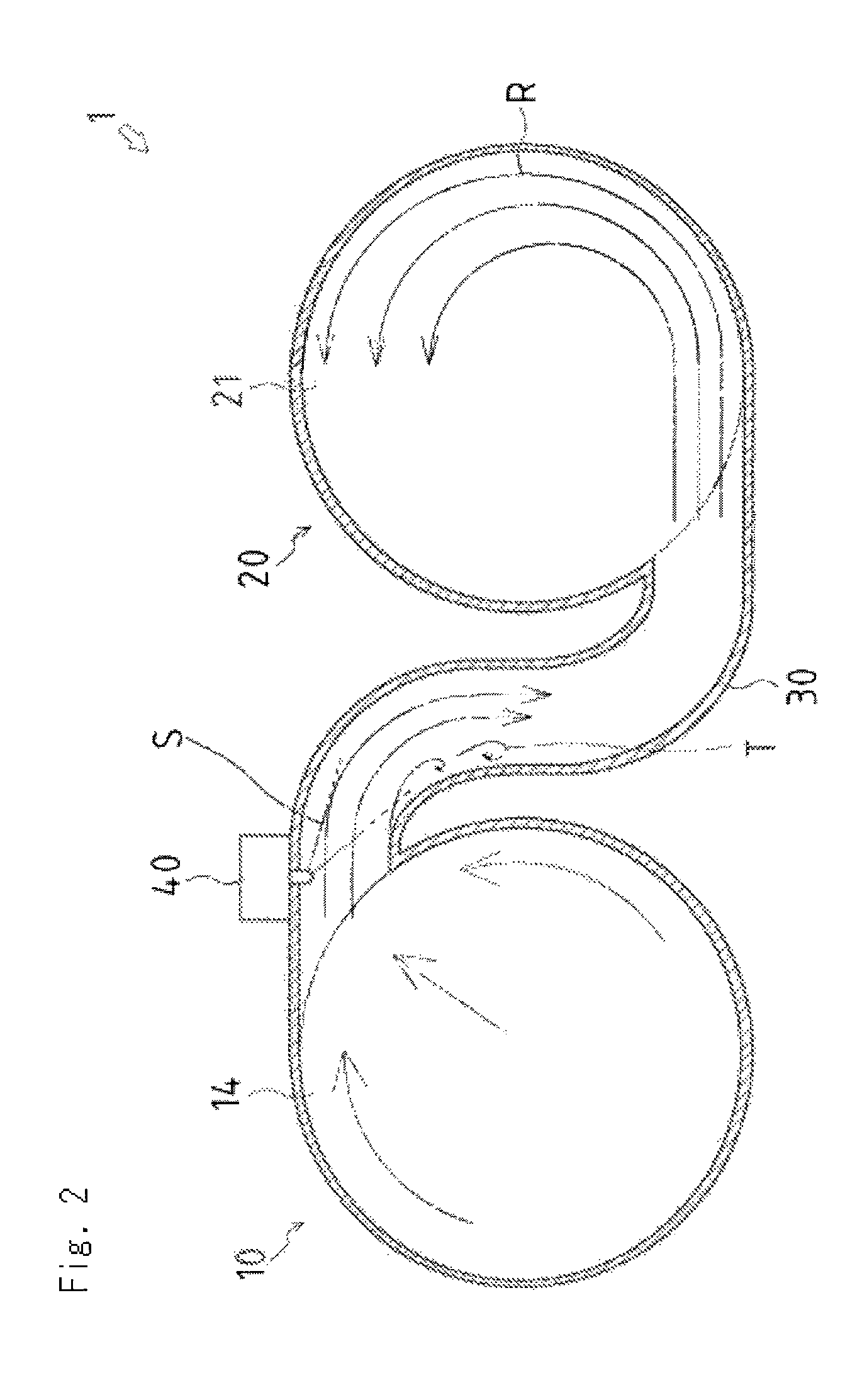
[0059]Similarly to the present invention, the upstream side of the communication pipe 30 is extended along the tangential direction of the first processing unit 10 while the axis of the communication pipe 30 at the connection part of the communication pipe 30 and the first processing unit 10 does not cross the axis of the first processing unit 10. The middle portion of the communication pipe 30 passes through the space between the first processing unit 10 and the second processing unit 20 at which the first processing unit 10 is the most close to the second processing unit 20. The downstream side of the communication pipe 30 is shifted to the position along the tangential direction of the second processing unit 20 while the axis of the communication pipe 30 does not cross the axis of the second processing unit 20, and is connected to the exhaust inlet provided in the inlet chamber 21 of the second processing unit 20.

[0060]In this case, the first processing unit 10 and the second pro...

second embodiment

[0062]Accordingly, in the second embodiment, the first processing unit 10 and the second processing unit 20 are arranged close to each other, whereby the exhaust purification apparatus 1 can be miniaturized further.

[0063]The exhaust gas to which the urea water S is supplied by the reducing agent supply unit 40 is contracted by the reduced diameter portion 30a and then expanded, whereby the evaporation and mixing of the urea water S can be promoted further. In the reduced diameter portion 30a positioned between the first processing unit 10 and the second processing unit 20, heat transmitted from the exhaust gas is hard to be dispersed so that respective high temperature can be maintained, whereby the evaporation of the urea water S can be promoted.

[0064]Furthermore, when the diesel engine is at low output driving state with small exhaust gas flow rate, the communication pipe 30 is provided so that the axis of the connection part of the communication pipe 30 and the first processing u...


PUM

PropertyMeasurementUnit
perimeteraaaaaaaaaa
diameteraaaaaaaaaa
timeaaaaaaaaaa

Abstract

An exhaust purification apparatus which comprises: a first processing unit for removing particulate matter; a second processing unit for reducing nitrogen oxide; a communication pipe for guiding exhaust from an exhaust outlet of the first processing unit to an exhaust inlet of the second processing unit; and a reducing agent supply unit on the communication pipe. The first and second processing units are arranged in parallel such that the exhaust outlet and the exhaust inlet are on the sides facing each other. The communication pipe is arranged between the first and second processing units where the processing units are closest to each other such that the upstream part of the communication pipe extends from the exhaust outlet along the outer circumferential surface of the first processing unit and the downstream part of the communication pipe extends along the outer circumferential surface of the second processing unit to the exhaust inlet.

Description

TECHNICAL FIELD[0001]The present invention relates to an art of an exhaust purification apparatus of a diesel engine.BACKGROUND ART[0002]Exhaust gas discharged from a diesel engine includes particle matter represented by soot and the like and nitrogen oxide represented by nitrogen monoxide and the like. As a means for removing the particle matter, a particle matter filter device which filters the exhaust gas with a filter carrier is known. As a means for removing the nitrogen oxide, a nitrogen oxide reductor is known as what reduces the nitrogen oxide with a reduction catalytic carrier after supplying urea water to the exhaust gas.[0003]In the case that the particle matter filter device and the nitrogen oxide reductor are employed as an exhaust purification apparatus so as to purify the exhaust gas discharged from the diesel engine, firstly, the particle matter in the exhaust gas is removed by the particle matter filter device, and then the nitrogen oxide is reduced by the nitrogen ...

Claims


Application Information

Patent Timeline
Patent Type & Authority Patents(United States)
IPC IPC(8): F01N3/00
CPCF01N2610/1453B01D2257/404F01N13/02B01D53/9431Y02T10/24B01D2258/012B01D53/944B01D2251/2067B01D53/9477F01N3/2066F01N3/0821F01N2470/30F01N2250/02F01N2610/02F01N2240/20F01N3/021F01N2240/18F01N2590/08F01N13/009Y02T10/12B01D53/94F01N3/02F01N3/08F01N3/24
Inventor OMOTE, HIROSHIOKADA, SHUSUKEKAWABATA, YUUJI
Owner YANMAR POWER TECHNOLOGY CO LTD
Why Eureka
Try Eureka