Pulsation damping system

a technology of damping system and pulsation, which is applied in the direction of liquid spraying apparatus, coatings, pipe elements, etc., can solve the problems of unusable large amounts of paint which have to be disposed of without being used, and achieve the effect of reducing both high-frequency and low-frequency pressure fluctuations, and being simple or small in construction

Active Publication Date: 2018-10-16
J WAGNER GMBH
View PDF4 Cites 2 Cited by
  • Summary
  • Abstract
  • Description
  • Claims
  • Application Information

AI Technical Summary

Benefits of technology

[0004]The object underlying the present invention is to develop a pulsation damping system or a paint spray device which is simple or small in construction and which reduces both high-frequency and low-frequency pressure fluctuations.
[0005]In the case of the pulsation damping system according to the present invention for a paint spray device for spraying paint, an opening of the chamber outlet is realized with a cross sectional area which is smaller than a cross sectional area of an opening of the chamber inlet. In a simple manner this forms a throttle, which damps the pulsation of the paint stream without at the same time forming a fairly large volume pressure accumulator which leads, during cleaning, to undesirably large amounts of paint which have to be disposed of without being used. The pressure accumulator having a small volume also prevents larger amounts of paint leaking once the paint spray device has been shut down if a spray head is actuated when the pump has been switched off. A pressure at the paint pump is also able to be reduced rapidly when the volume of the pressure accumulator is small.

Problems solved by technology

In a simple manner this forms a throttle, which damps the pulsation of the paint stream without at the same time forming a fairly large volume pressure accumulator which leads, during cleaning, to undesirably large amounts of paint which have to be disposed of without being used.

Method used


Image

  • Pulsation damping system
  • Pulsation damping system
  • Pulsation damping system

Examples


Embodiment Construction

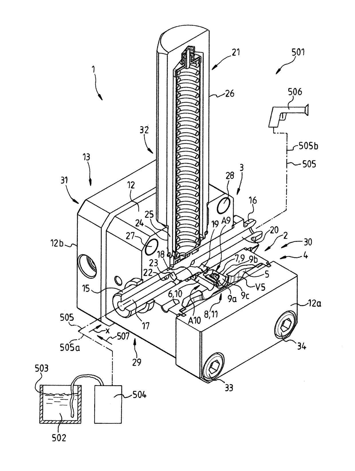
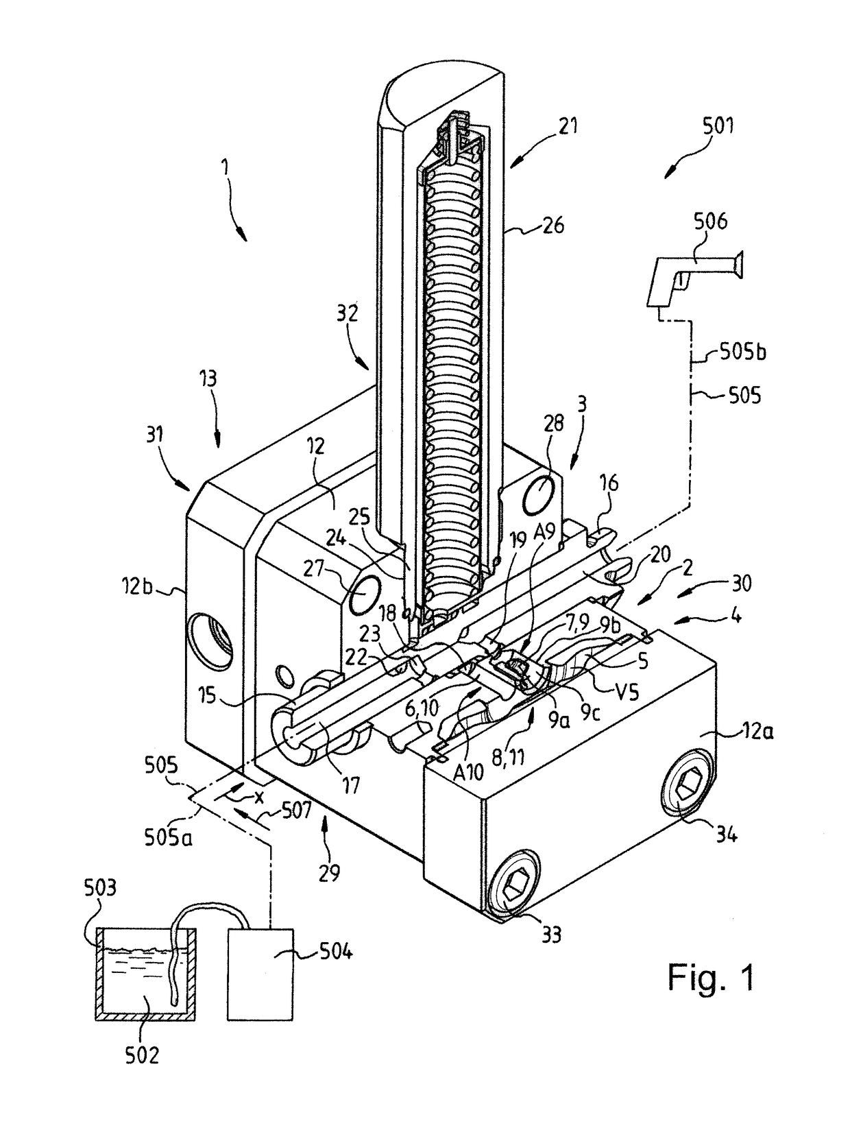
[0030]FIG. 1 shows a perspective and part-cutaway view of a pulsation damping system 1 according to the present invention. Cut surfaces are not hatched in the representation to retain clarity.

[0031]The pulsation damping system 1 is a component part of a paint spray device 501 for spraying paint 502 which is shown schematically in FIG. 1. Along with the pulsation damping system 1, the paint spray device 501 includes a paint container 503, a paint pump 504, a paint hose 505 and a spray head 506. In this connection, a first portion 505a of the paint hose 505 leads from the paint pump 504 to the pulsation damping system 1 and a second portion 505b of the paint hose 505 leads from the pulsation damping system 1 to the spray head 506. The pulsation damping system 1 includes a pulsation damper 2. The pulsation damper serves for damping the pulsation of a paint stream 507 flowing from the paint pump 504 to the spray head 505. The pulsation of the paint stream 507 is determined essentially b...


PUM


Abstract

The present invention relates to a pulsation damping system for a paint spray device for spraying paint including a pulsation damper for damping the pulsation of a paint stream, wherein the pulsation damper includes a housing, a chamber, a chamber inlet, a chamber outlet and a damping means. In this connection, an opening of the chamber outlet comprises a cross sectional area which is smaller than a cross sectional area of an opening of the chamber inlet, and as a result forms a throttle.

Description

[0001]This application claims the benefit under 35 USC § 119(a)-(d) of German Application No. 10 2015 110 883.6 filed Jul. 6, 2015, the entirety of which is incorporated herein by reference.FIELD OF THE INVENTION[0002]The present invention relates to a pulsation damping system as well as to a paint spray device.BACKGROUND OF THE INVENTION[0003]DE 87 15 311 U1 discloses a pulsation damping system for a paint spray device for spraying paint which includes a pulsation damper for damping the pulsation of a paint stream, the pulsation damper including a housing, a chamber, a chamber inlet, a chamber outlet and a damping means.SUMMARY OF THE INVENTION[0004]The object underlying the present invention is to develop a pulsation damping system or a paint spray device which is simple or small in construction and which reduces both high-frequency and low-frequency pressure fluctuations.[0005]In the case of the pulsation damping system according to the present invention for a paint spray device ...

Claims


Application Information

Patent Timeline
Patent Type & Authority Patents(United States)
IPC IPC(8): F16L55/04F15D1/02F04B11/00F04B23/00F04B15/02F16L55/053B05C11/10B05B15/18
CPCF15D1/02F04B11/00F04B11/0008F04B11/0016F04B11/0033F04B15/02F04B23/00F04B11/0091F16L55/053B05C11/1047F16L55/04B05B9/047B05B12/06B05B9/0413B05B15/18
Inventor WUERPEL, HARTMUT
Owner J WAGNER GMBH
Why Eureka
Try Eureka