Wideband antenna using coupling matching

a wideband antenna and coupling technology, applied in the field of wideband antennas, can solve the problems of difficult design of the exterior of the terminal, unresearched internal structure of the helical antenna, and unsatisfactory sar characteristics, and achieve the effect of low profile characteristics and wide band characteristics

Inactive Publication Date: 2012-02-02
ACE TECH
View PDF4 Cites 14 Cited by
  • Summary
  • Abstract
  • Description
  • Claims
  • Application Information

AI Technical Summary

Benefits of technology

[0021]Certain aspects of the present invention can provide an antenna that has wide-band characteristics as well as low profile characteristics.

Problems solved by technology

While this type of antenna has the advantage of high gain, its non-directivity results in undesirable SAR characteristics, which form the criteria for levels of electromagnetic radiation hazardous to the human body.
Also, since the helical antenna is formed protruding outwards of the terminal, it is difficult to design the exterior of the terminal to be aesthetically pleasing and suitable for carrying, but a internal structure for the helical antenna has not yet been researched.
However, the inverted-F antenna may have a narrow frequency bandwidth when it is designed to operate in multiple bands.

Method used


Image

  • Wideband antenna using coupling matching
  • Wideband antenna using coupling matching
  • Wideband antenna using coupling matching

Examples


Embodiment Construction

[0031]The wide-band antenna using coupling according to certain embodiments of the present invention will be described below in more detail with reference to the accompanying drawings.

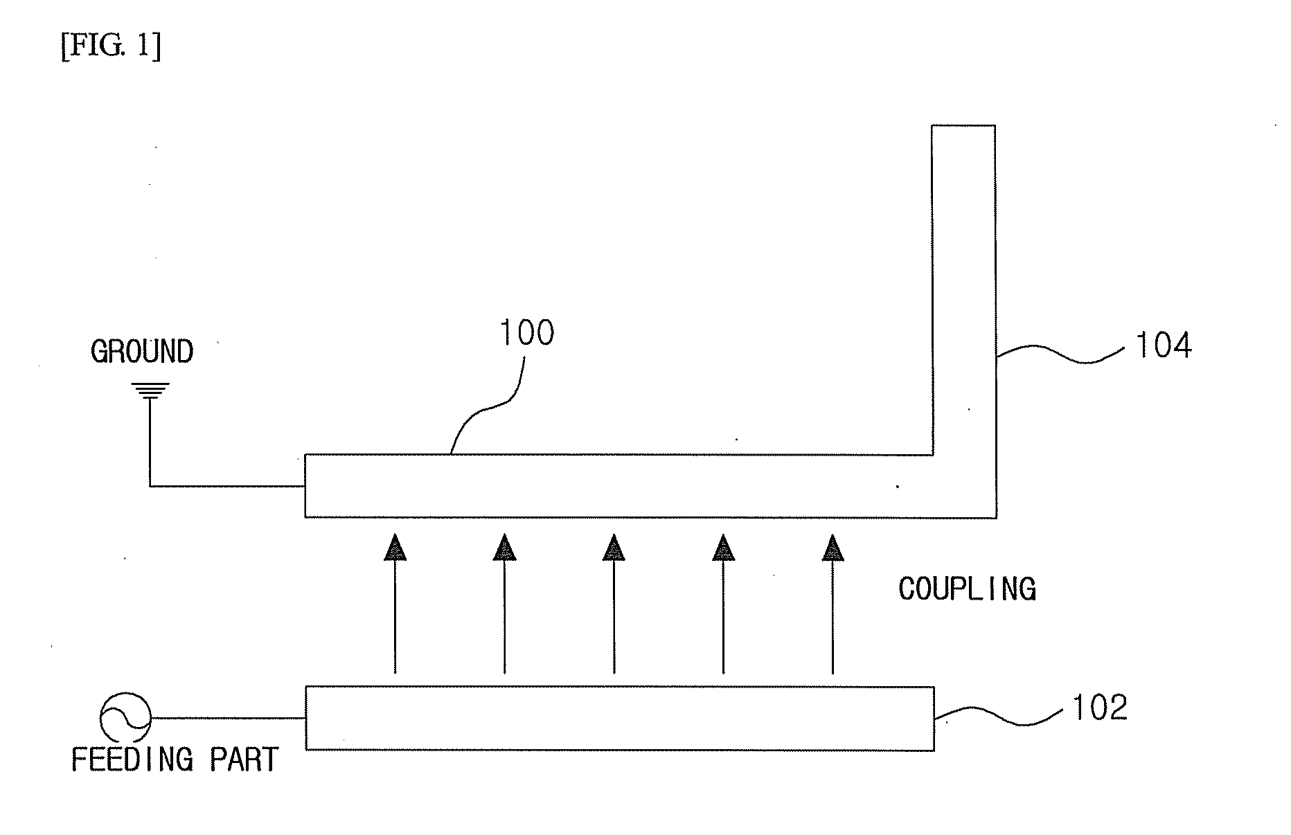
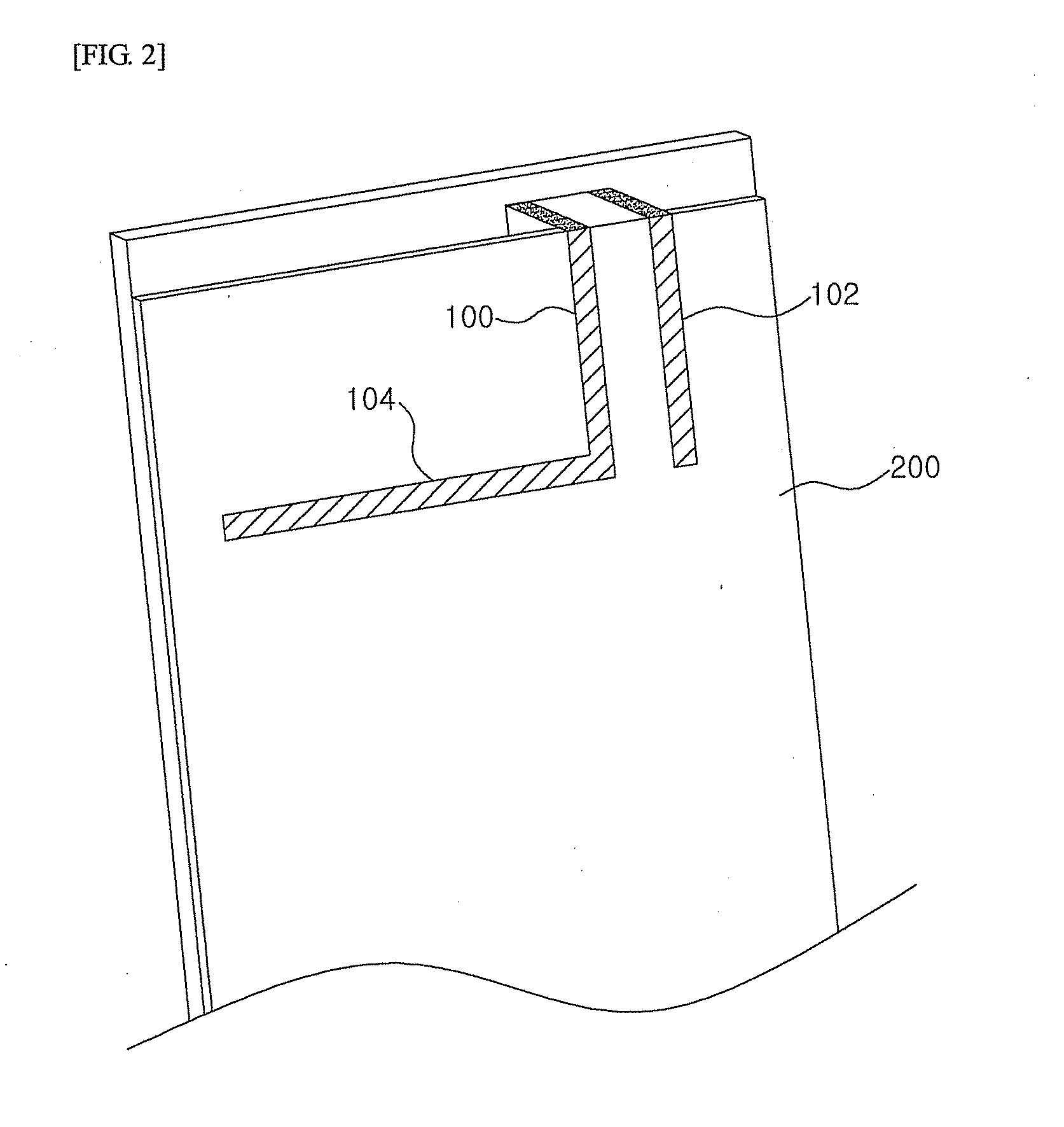
[0032]FIG. 1 schematically illustrates the structure of an internal wide-band antenna using coupling according to a first disclosed embodiment of the present invention, and FIG. 2 illustrates an example of a internal wide-band antenna using coupling according to the first disclosed embodiment of the present invention implemented on a carrier.

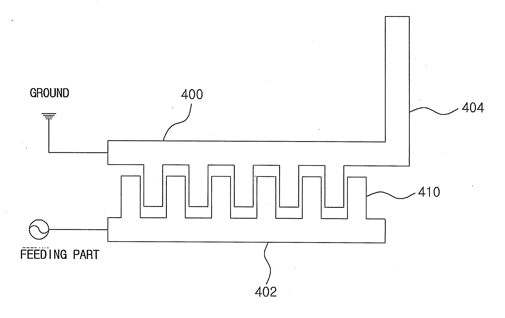
[0033]Referring to FIG. 1, a wide-band antenna according to the first disclosed embodiment of the present invention may include a first conductive element 100 electrically coupled to a ground, a second conductive element 102 electrically coupled to a feeding part, and a third conductive element 104 extending from the first conductive element 100.

[0034]The first conductive element 100 coupled to the ground and the second conductive element 102 coupled to the feeding...


PUM


Abstract

A wide-band antenna using coupling matching is disclosed. The antenna may include a first conductive element, which is electrically connected with a ground; a second conductive element, which is electrically connected with a power feed point and formed parallel to the first conductive element with a particular distance in-between; and a third conductive element for emitting an RF signal that extends from the first conductive element, where the first conductive element and the second conductive element have a particular length such that progressive waves are generated and sufficient coupling is achieved. According to certain aspects of the present invention, a internal type multi-band antenna having wide-band characteristics can be provided, by using coupling matching for multi-band design.

Description

TECHNICAL FIELD[0001]The present invention relates to an antenna, more particularly to an antenna that supports impedance matching for wide-band applications.BACKGROUND ART[0002]In current mobile terminals, there is a demand not only for smaller sizes and lighter weight, but also for functions that allow a user access to mobile communication services of different frequency bands through a single terminal. That is, there is a demand for a terminal with which a user may simultaneously utilize signals of multiple bands as necessary, from among mobile communication services of various frequency bands, such as the CDMA service based on the 824˜894 MHz band and the PCS service based on the 1750˜1870 MHz band commercialized in Korea, the CDMA service based on the 832˜925 MHz band commercialized in Japan, the PCS service based on the 1850˜1990 MHz commercialized in the United States, the GSM service based on the 880˜960 MHz band commercialized in Europe and China, and the DCS service based ...

Claims


Application Information

Patent Timeline
Patent Type & Authority Applications(United States)
IPC IPC(8): H01Q1/50H01Q5/15H01Q5/335H01Q5/385H01Q5/50
CPCH01Q9/16H01Q9/42H01Q5/50H01Q5/335H01Q5/385H01Q1/243H01Q5/22
Inventor LEE, SEUNG-CHEOLKIM, BYONG-NAMJUNG, JONG-HO
Owner ACE TECH
Why Eureka
Try Eureka