Multi band indoor antenna

a multi-band indoor antenna and antenna technology, applied in the field of indoor antennas, can solve the problems of large horizontal component, large cost of implementation, and large cost of elements, and achieve the effects of low cost, uniform performance, and small size implementation

Active Publication Date: 2010-05-04
CORNING OPTICAL COMM WIRELESS
View PDF9 Cites 17 Cited by
  • Summary
  • Abstract
  • Description
  • Claims
  • Application Information

AI Technical Summary

Benefits of technology

[0008]The present invention discloses a unique and novel omni-directional antenna able to truly provide wide-band characteristics and uniform performance with low cost and small size implementation.

Problems solved by technology

Second, in an indoor environment, wave polarization is impacted by reflections, diffraction and scattering, thus creating a significant horizontal component.
Most, such as Yagi, log periodic or fractal element-based antennas, require relatively complicated structures which are expensive to implement.
However, such elements are expensive to produce.
However, the demanding wireless market requires continued miniaturization and increased operating bandwidth.
Nevertheless these solutions, which use several resonance frequencies established by parasitic and multi-element construction, are not truly wide band.
[5]), thereby enforcing a non-optimal frequency and spatial coverage.

Method used


Image

  • Multi band indoor antenna
  • Multi band indoor antenna
  • Multi band indoor antenna

Examples


Embodiment Construction

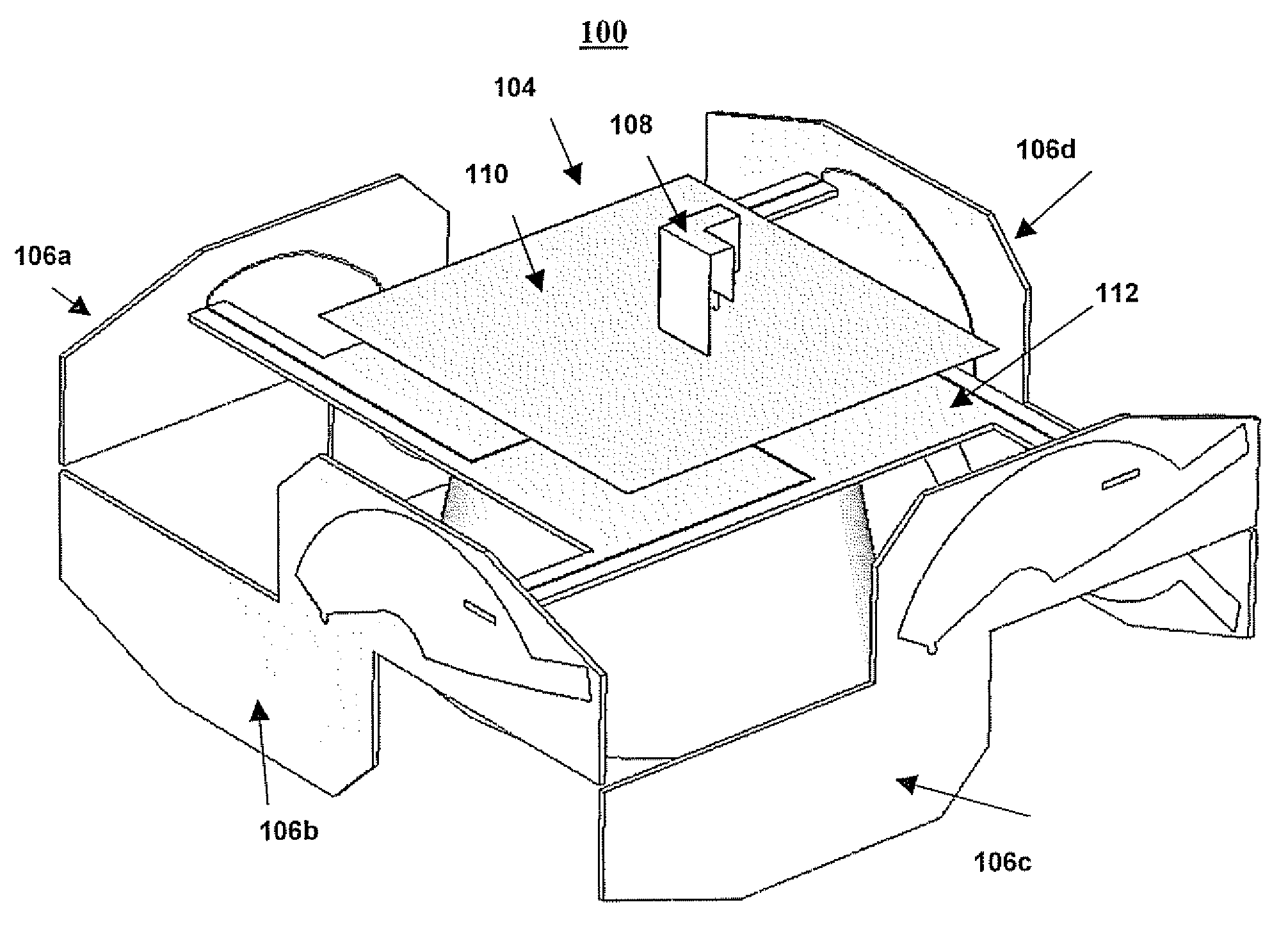
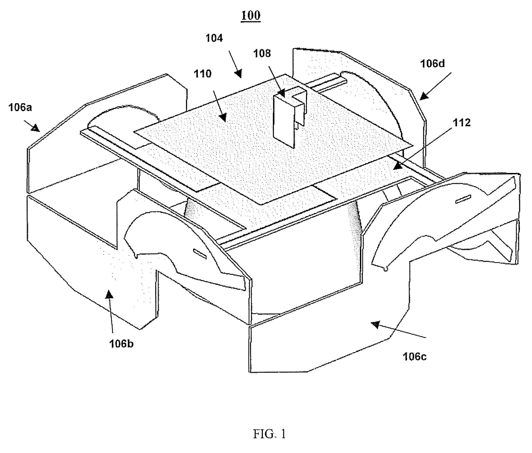
[0037]The present invention is of a wide band, omni-directional antenna that includes two novel sections—a low band section and a high band section combined and fed by a novel component. The low and high band sections may serve as antennas for respective frequency bands on their own. The wide band, omni-directional antenna of the present invention (also referred to herein as an indoor antenna) provides high power density directed towards the antenna plane and lower power densities directed perpendicular to the antenna planes The polarization varies between near circular to highly elliptical, depending on the frequency band. The polarization vector lies in the plane perpendicular to the antenna plane. The indoor antenna thus has advantageous properties in an indoor environment.

[0038]The principles and operation of the indoor antenna according to the present invention may be better understood with reference to the drawings and the accompanying description.

[0039]FIG. 1 shows the constr...


PUM


Abstract

A wide band indoor antenna includes a low band section with four modified spiral (MSE) elements, a high band section with a bent folded monopole (BFM) radiator mounted on a ground plane and a feeding plate for feeding the low band section and the high band section via a diplexer. The BFM radiator mounted on the ground plane can serve independently as a high frequency monopole antenna.

Description

CROSS REFERENCE TO RELATED APPLICATIONS[0001]The present invention claims priority from U.S. Provisional Patent Application No. 60 / 735,867, filed 14 Nov. 2005, the contents of which are incorporated herein by referenceFIELD AND BACKGROUND OF THE INVENTION[0002]The present invention refers in general to antennas and in particular to indoor antennas.[0003]Efficient electromagnetic wave propagation, within al indoor environment, requires special attention to antenna pattern aid polarization. The effect of these two factors may be intuitively understood. First, due to the “Near-Far” effect, the antenna needs to emphasize power density towards relatively farther away (distant) users while de-emphasizing power density directed towards relatively close users. Second, in an indoor environment, wave polarization is impacted by reflections, diffraction and scattering, thus creating a significant horizontal component.[0004]Wide band antenna operation may be achieved by many methods and antenna...

Claims


Application Information

Patent Timeline
Patent Type & Authority Patents(United States)
IPC IPC(8): H01Q1/38
CPCH01Q1/007H01Q9/27H01Q21/30H01Q21/20H01Q21/28H01Q9/42
Inventor SABAN, OFERALMOG, BENNY
Owner CORNING OPTICAL COMM WIRELESS
Why Eureka
Try Eureka