
Liquid ejection apparatus

Active Publication Date: 2012-02-02
BROTHER KOGYO KK
View PDF1 Cites 3 Cited by
  • Summary
  • Abstract
  • Description
  • Claims
  • Application Information

AI Technical Summary

Benefits of technology

[0007]This invention has been developed in view of the above-described situations, and it is an object of the present invention to provide a liquid ejection apparatus configured to efficiently discharge liquid and air bubbles and the like from ejection openings while preventing unnecessary consumption of the liquid.
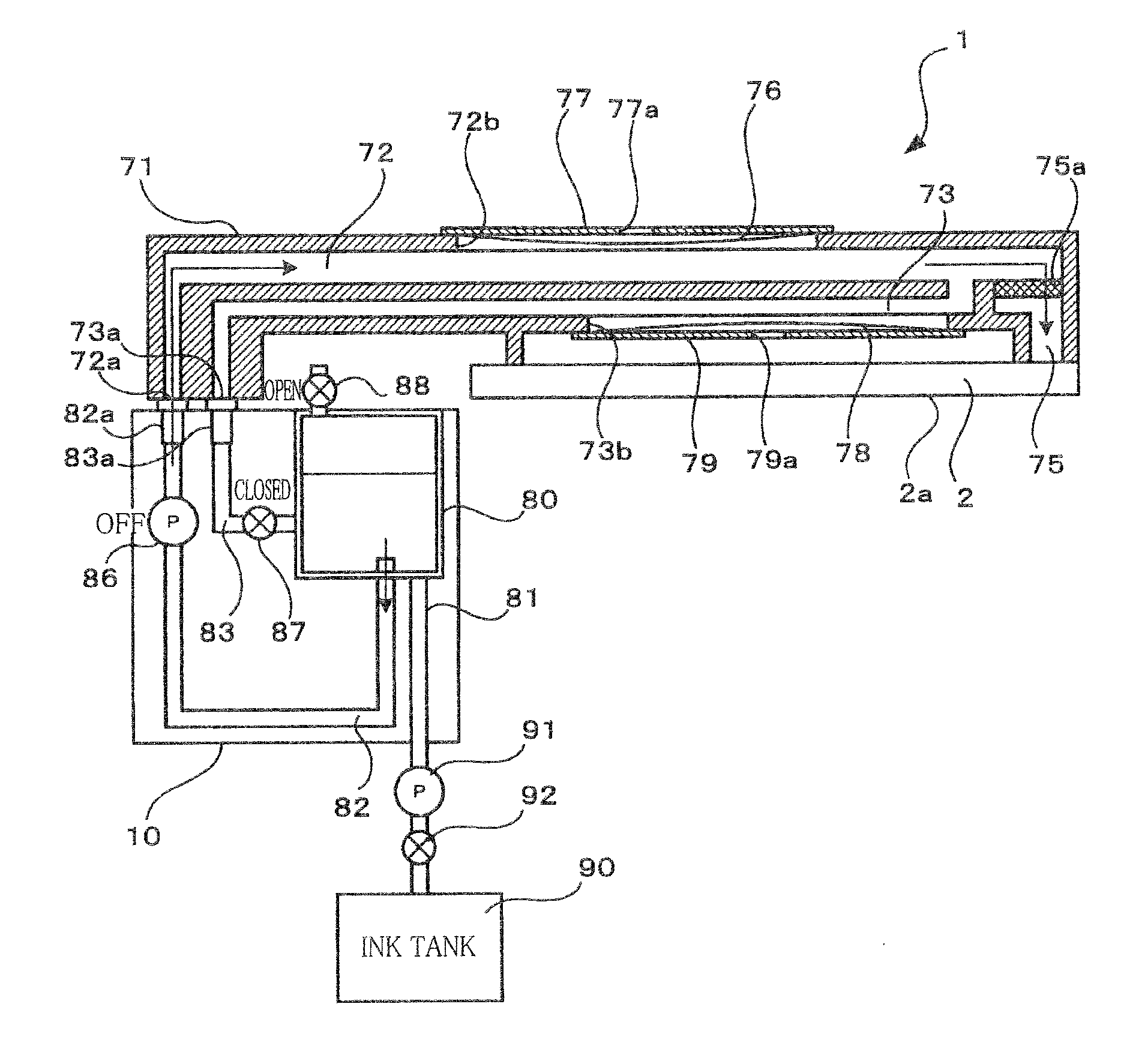
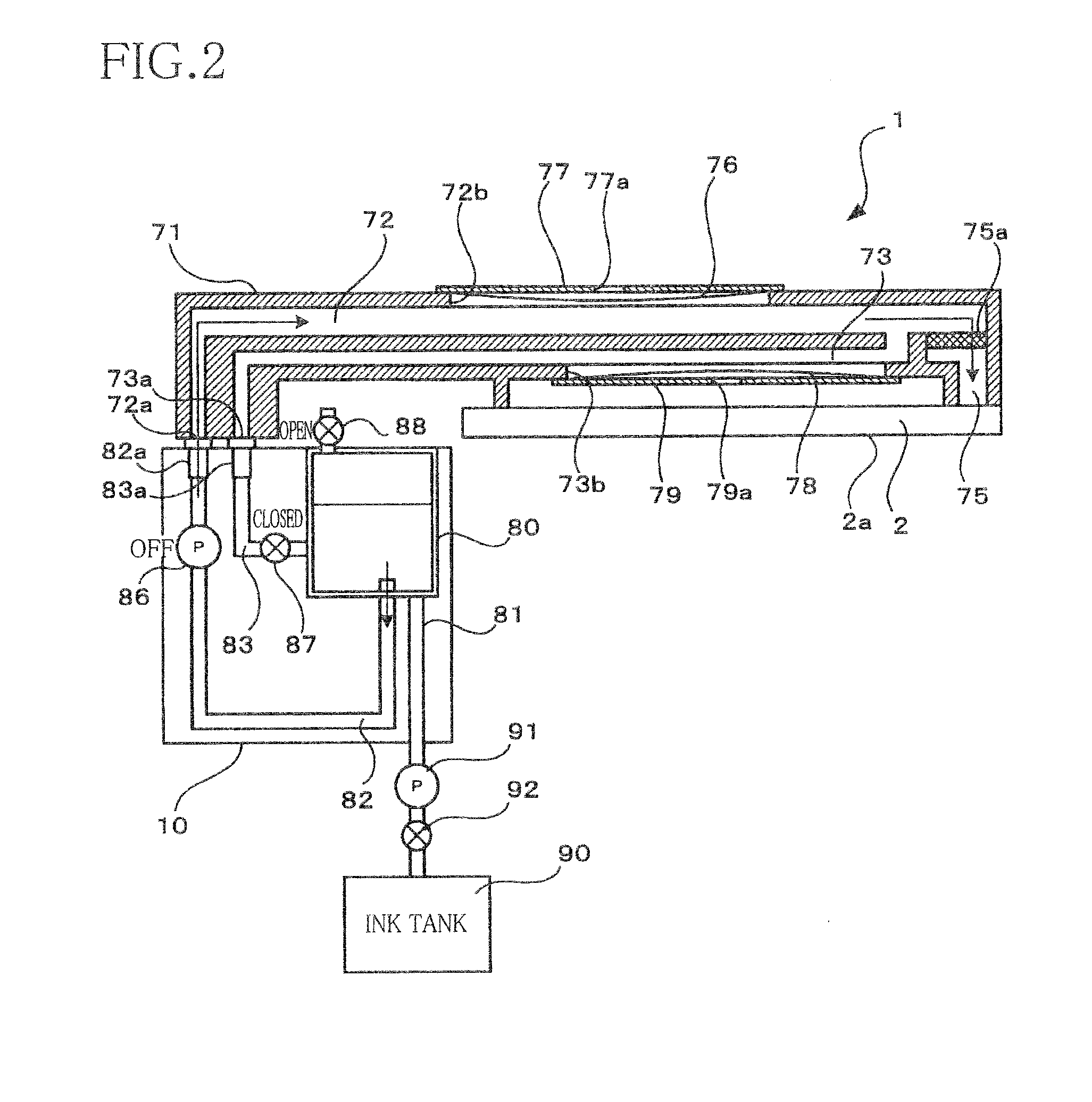
[0010]In the image liquid ejection apparatuses constructed as described above, air bubbles, foreign matters, and the like remaining in the inside channel can be discharged into the tank by the liquid circulation while preventing the liquid from leaking from the ejection openings. Further, the channel resistance value is increased by the adjustment of the adjusting device in this state to momentarily increase a pressure in the inside channel, whereby the liquid in the inside channel flows into the individual channels so as to be discharged from the ejection openings. In this operation, a relatively high pressure is applied to all the ejection openings from the start of the liquid discharge control to discharge the liquid in the ejection openings. Accordingly, it is possible to efficiently discharge thickened liquid in the ejection openings, the air bubbles, and the foreign matters, and it is possible to prevent the liquid from being discharged needlessly. Further, the unit-time supply amount at an end of the liquid discharge control is less than that in the liquid circulation control. Thus, even where a meniscus withstanding pressure of a meniscus formed in the ejection openings has been lowered because the liquid discharged in a previous discharging has adhered to defining portions of the ejection openings, it is possible to prevent the liquid from leaking from the ejection openings after the end of discharging of the liquid.

Problems solved by technology

This makes it impossible to instantaneously discharge the ink from all the ejection openings at the same time.
Further, since meniscus withstanding pressures of the ejection openings are lowered by adhesion of the discharged ink to portions defining the ejection openings, the ink may leak from the ejection openings also by slight ink flow in the ink channels, leading to unnecessary ink discharge.

Method used


Image

  • Liquid ejection apparatus
  • Liquid ejection apparatus
  • Liquid ejection apparatus

Examples


Embodiment Construction

[0025]Hereinafter, there will be described an embodiment of the present invention by reference to the drawings.

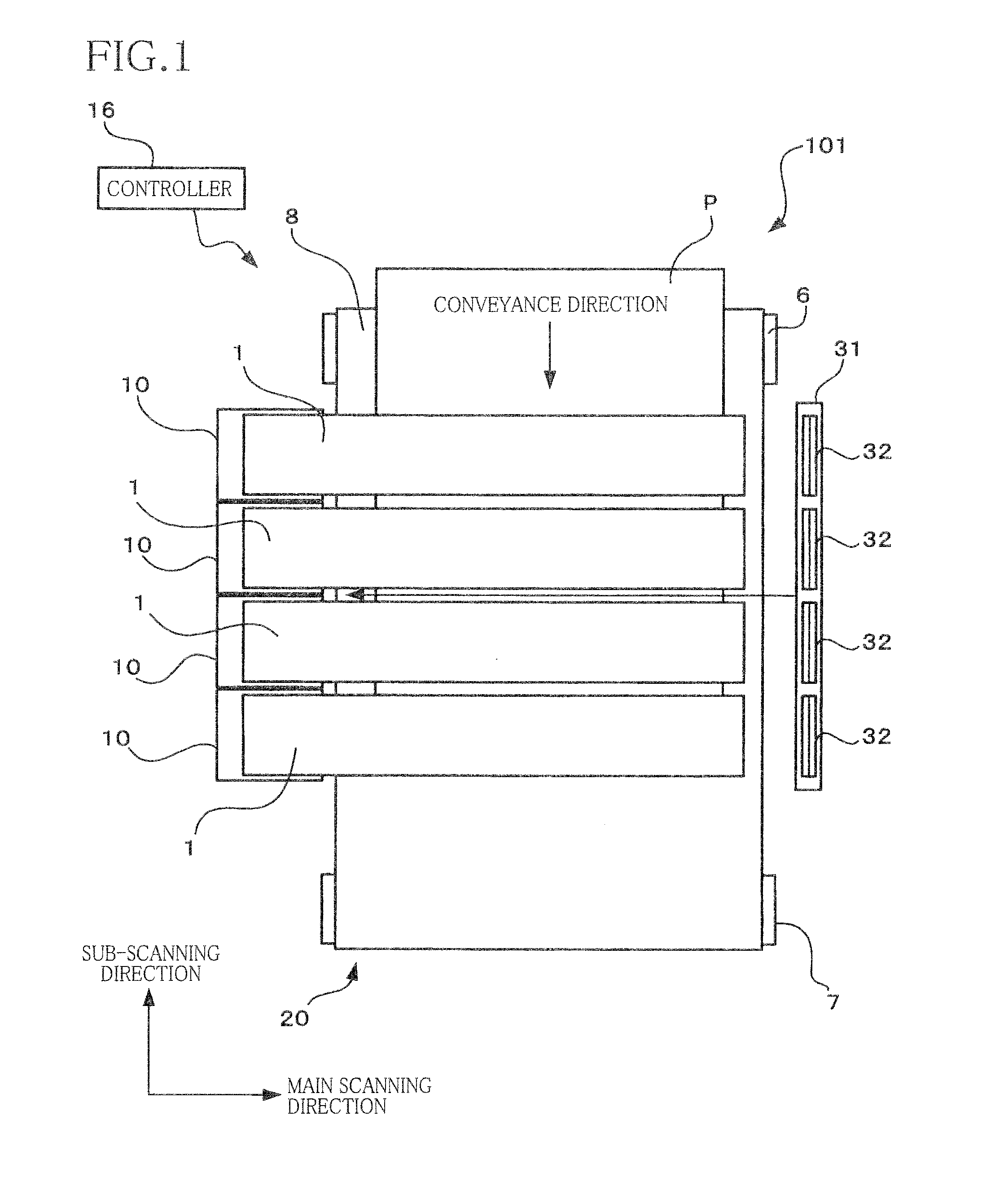
[0026]As shown in FIG. 1, an ink jetprinter 101 as one example of a liquid ejection apparatus includes: (a) a sheet conveyance unit 20 configured to convey a sheet P from an upper side toward a lower side in FIG. 1; (b) four ink jetheads 1 (each as one example of liquid ejection head) configured to eject droplets of inks of respective four colors, namely, black, magenta, cyan, and yellow onto the sheet P conveyed by the conveyance unit 20; four ink supply units 10 configured to respectively supply the inks to the ink-jet heads 1; a maintenance unit 31 configured to perform a maintenance for ink jetheads 1; and a controller 16 configured to control entire operations of the ink jet printer 101. It is noted that, in the present embodiment, a sub-scanning direction is a direction parallel to a conveyance direction in which the conveyance unit 20 conveys the sheet P, and a main ...


PUM


Abstract

A liquid ejection apparatus including: a liquid ejection head including an inside channel; a supply channel; a return channel; a supply device; an adjusting device; and a controller, wherein the controller starts a liquid circulation control for circulating liquid through the supply channel, the inside channel, and the return channel in order by controlling: the adjusting device such that a channel resistance value of the return channel is less than a predetermined maximum value; and the supply device to supply the liquid into the inside channel, wherein, when the liquid is circulated, the controller starts a liquid discharge control for discharging the liquid by increasing the channel resistance value, wherein, when the liquid is discharged, the controller starts a liquid-discharge stopping control for stopping the discharge by decreasing the channel resistance value, and wherein the controller controls the supply device such that a liquid amount supplied to the inside channel per unit time when the discharge is stopped is less than that in the liquid circulation control.

Description

CROSS REFERENCE TO RELATED APPLICATION[0001]The present application claims priority from Japanese Patent Application No. 2010-172237, which was filed on Jul. 30, 2010, the disclosure of which is herein incorporated by reference in its entirety.BACKGROUND OF THE INVENTION[0002]1. Field of the Invention[0003]The present invention relates to a liquid ejection apparatus configured to eject liquid from ejection openings.[0004]2. Description of the Related Art[0005]There is known an ink jethead configured to eject ink droplets from a plurality of ejection openings and perform a cleaning for the ejection openings by forcibly supplying the ink into ink channels in the ink-jet head by a pump and to discharge air bubbles and thickened or viscous ink remaining in portions of the ink channels which are located near the ejection openings. For example, after a three-way valve is closed to close and seal a discharging passage, a supply pump is operated to pressurize the ink in the ink channels for...

Claims


Application Information

Patent Timeline
IPC IPC(8): B41J29/38
CPCB41J2/16526B41J2/20B41J2/19B41J2/18
Inventor IGARASHI, AKINORI
Owner BROTHER KOGYO KK
Learn More