Apparatus and method for supporting range expansion in a wireless network

a wireless network and wireless network technology, applied in the field of wireless networks, can solve the problems of large imbalance between downlink and uplink coverage regions, micro-bss may potentially cover most of the cell, and it is completely impossible for micro-base stations to serve data to mobile stations in its expanded rang

Inactive Publication Date: 2012-02-02
SAMSUNG ELECTRONICS CO LTD
View PDF3 Cites 111 Cited by
  • Summary
  • Abstract
  • Description
  • Claims
  • Application Information

AI Technical Summary

Problems solved by technology

Additionally, a large number of new cell-edges areas are created with the introduction of micro-BSs, because mobile stations that normally are in the same cell—and hence orthogonal to each other—now use the same resources and interfere with each other.
However, this increased bandwidth can be used by only a small fraction of mobile stations which fall within the small coverage region of the micro-BSs.
Thus, the presence of base station with different transmit powers creates a large degree of imbalance between the downlink and uplink coverage regions.
Moreover, these micro-BSs may potentially cover most of the cell in the absence of interference from the macro-BS.
Note that without such coordination, it may be completely impossible for the micro-base station to serve any data to mobile stations in its expanded range, since the SINR of the mobile stations, taking macro-BS interference into account, is extremely low.
In a heterogeneous network deployment in which macro-cells and micro-cells use a single component carrier, the RE-MS may receive a high level of interference from the macro-cell.
However, the interference from the common reference signal (CRS) portions of the macro-cell still remains.
However, as indicated above, with range expansion, where a RE-MS is allowed to be attached to a low-power node while experiencing significantly low geometry (−16 dB), the RE-MS may not able to decode the PCFICH of the low-power node (i.e., the micro-BS).
Furthermore, the network may comprise mobile stations that may or may not support range expansion.

Method used


Image

  • Apparatus and method for supporting range expansion in a wireless network
  • Apparatus and method for supporting range expansion in a wireless network
  • Apparatus and method for supporting range expansion in a wireless network

Examples


Embodiment Construction

[0028]FIGS. 1 through 3, discussed below, and the various embodiments used to describe the principles of the present disclosure in this patent document are by way of illustration only and should not be construed in any way to limit the scope of the disclosure. Those skilled in the art will understand that the principles of the present disclosure may be implemented in any suitably arranged wireless communication system.

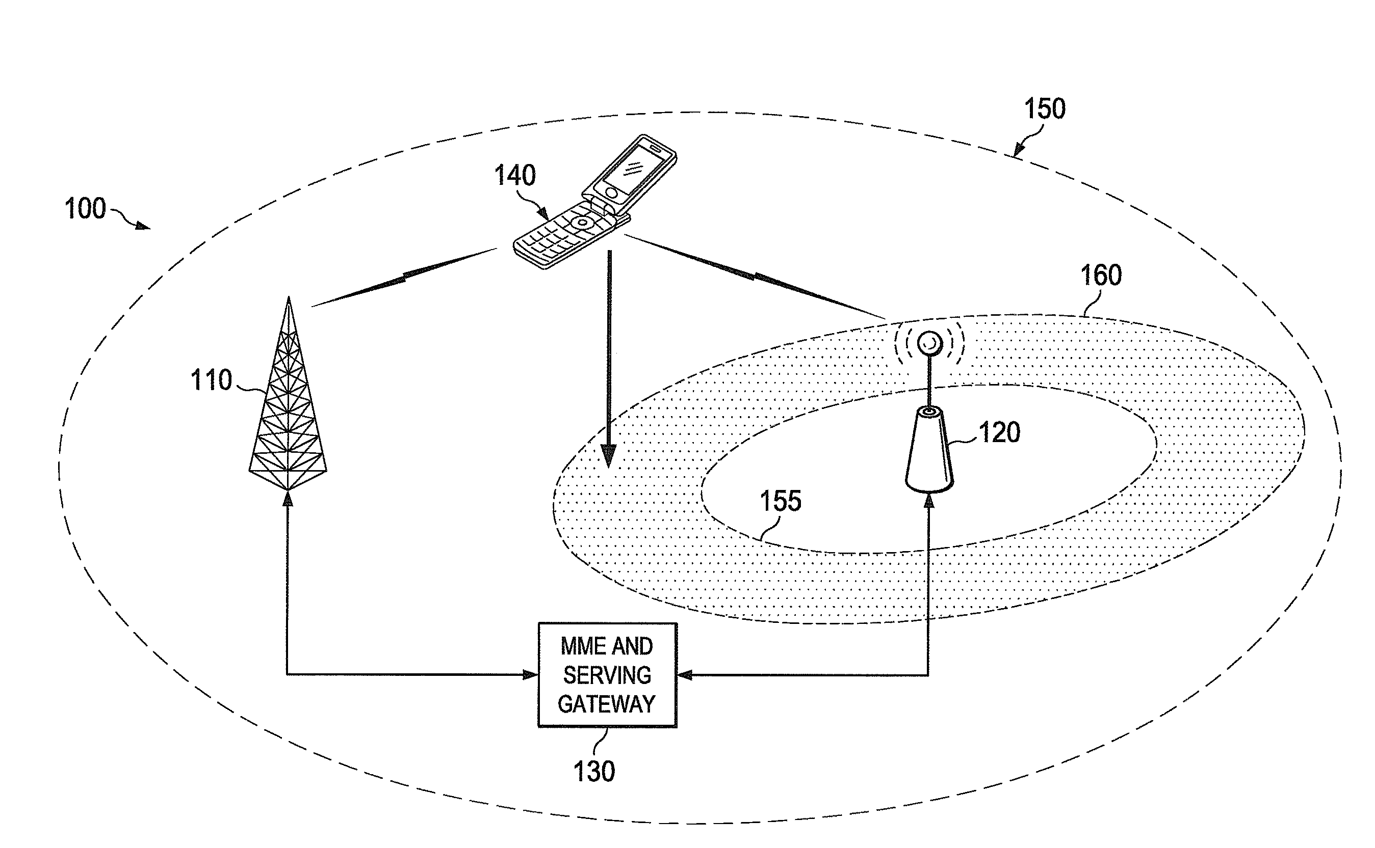
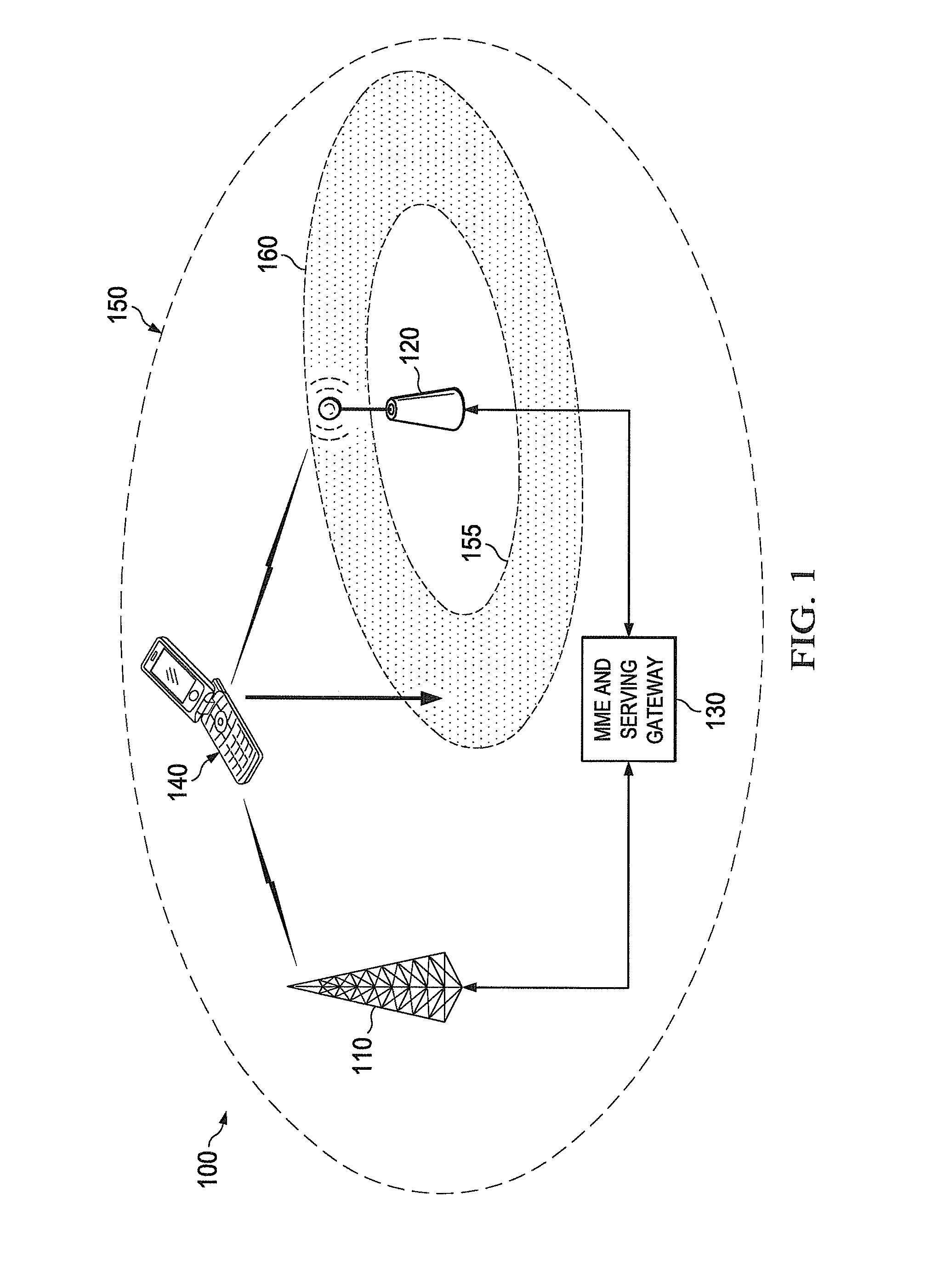
[0029]FIG. 1 illustrates wireless network 100 in which a microbase station operates in the coverage area of a macro-base station according to an exemplary embodiment of the disclosure. Wireless network 100 comprises macro-base station 110, micro-base station 120, and MME & serving gateway 130. Macro-BS 110 and micro-BS 120 both communicate via the same MME & serving gateway 130. Coverage area 150 of macro-BS 110 is indicated by a dotted line oval. Coverage area 155 of micro-BS 120 is indicated by a sold line oval.

[0030]Mobile station (MS) 140 operates in coverage area ...


PUM


Abstract

A wireless network for communicating with a mobile station capable of operating in a range expansion mode. The wireless network comprises a macro-base station (BS) operable to communicate with the mobile station and a micro-base station (BS) in a coverage area associated with the macro-BS. The macro-BS transmits to the micro-BS a first control message indicating a range expansion (RE) capability of the mobile station. In response, the micro-BS transmits to the macro-BS PCFICH information associated with the micro-BS. The macro-BS transmits the PCFICH information to the mobile station and the mobile station uses the PCFICH information to perform a handover procedure to the micro-BS.

Description

CROSS-REFERENCE TO RELATED APPLICATION(S) AND CLAIM OF PRIORITY[0001]The present application is related to U.S. Provisional Patent. Application No. 61 / 370,006, filed Aug. 2, 2010, entitled “PCFICH SUPPORT FOR RANGE EXPANSION”, and U.S. Provisional Patent Application No. 61 / 373,213, filed Aug. 12, 2010, entitled “PCFICH SUPPORT FOR RANGE EXPANSION”. Provisional Patent Applications No. 61 / 370,006 and 61 / 373,213 are assigned to the assignee of the present application and are hereby incorporated by reference into the present application as if fully set forth herein. The present application hereby claims priority under 35 U.S.C. §119(e) to U.S. Provisional Patent Application No. 61 / 370,006 and U.S. Provisional Patent Application No. 61 / 373,213.TECHNICAL FIELD OF THE INVENTION[0002]The present application relates generally to wireless networks and, more specifically, to systems and methods for supporting range expansion of a micro-base station in the coverage area of a macro-base station ...

Claims


Application Information

Patent Timeline
Patent Type & Authority Applications(United States)
IPC IPC(8): H04W36/00
CPCH04W36/04H04W36/0072
Inventor MIAO, GUOWANGLI, YINGZHANG, JIANZHONGNAM, YOUNG-HANLIU, LINGJIAJEONG, KYEONG-INNG, BOON LOONG
Owner SAMSUNG ELECTRONICS CO LTD
Why Eureka
Try Eureka