Reduced Footprint Microphone System with Spacer Member Having Through-Hole

a microphone and spacer technology, applied in the field of microchips, can solve the problems of inoperable devices, therefore the footprint of the package,

Active Publication Date: 2012-02-02
INVENSENSE
View PDF7 Cites 57 Cited by
  • Summary
  • Abstract
  • Description
  • Claims
  • Application Information

AI Technical Summary

Problems solved by technology

The package thus must have a footprint that is large enough to hold both the microphone chip and the integrated circuit chip.
Such clean microstructure surfaces, however, can stick together if they come into contact.
When the surfaces remain stuck together, the device often is inoperable.
For example, flux / solder that secures the MEMS microphone to the circuit board may inadvertently contact the movable microstructure, causing stiction.

Method used


Image

  • Reduced Footprint Microphone System with Spacer Member Having Through-Hole
  • Reduced Footprint Microphone System with Spacer Member Having Through-Hole
  • Reduced Footprint Microphone System with Spacer Member Having Through-Hole

Examples


Embodiment Construction

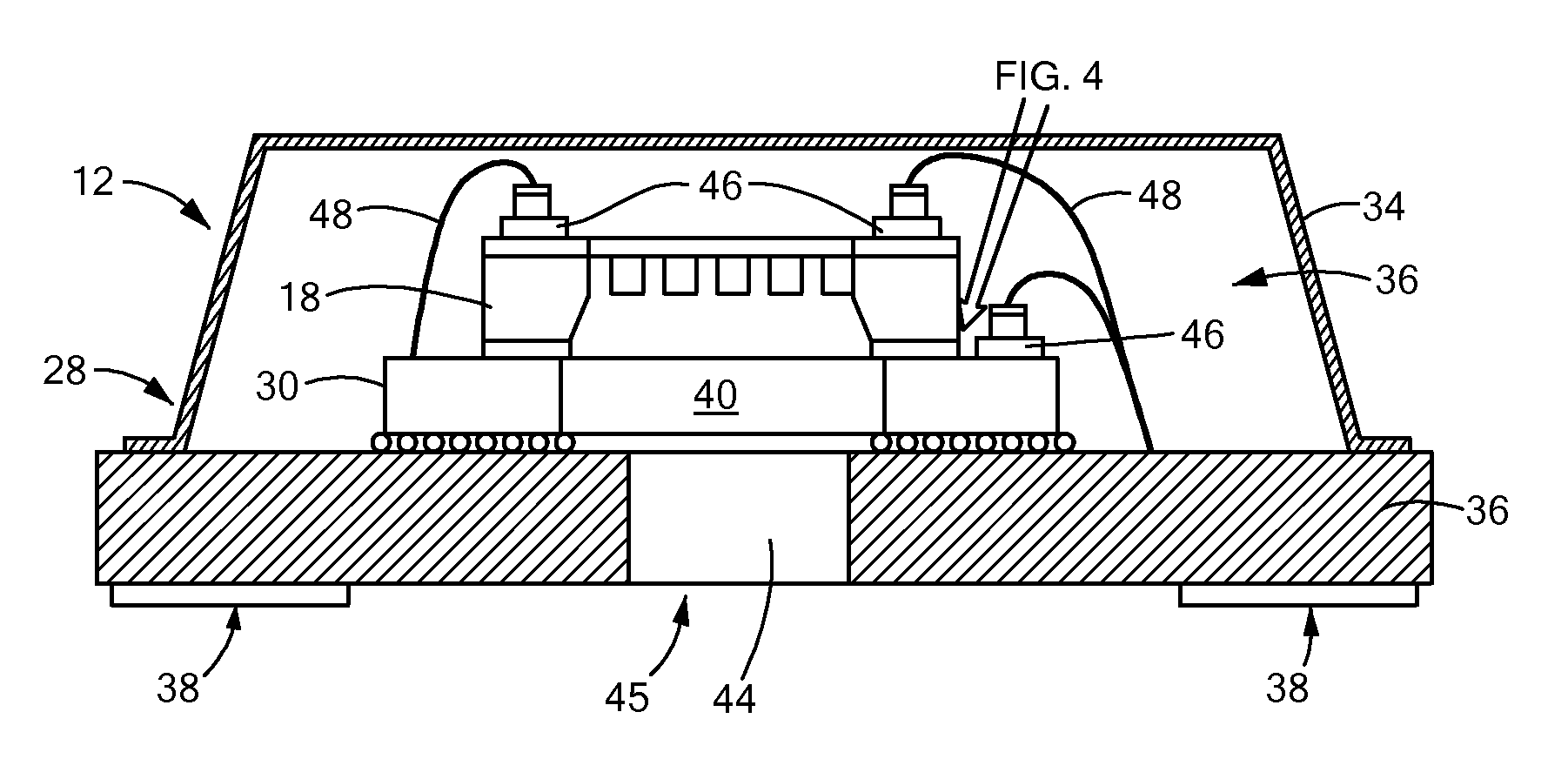
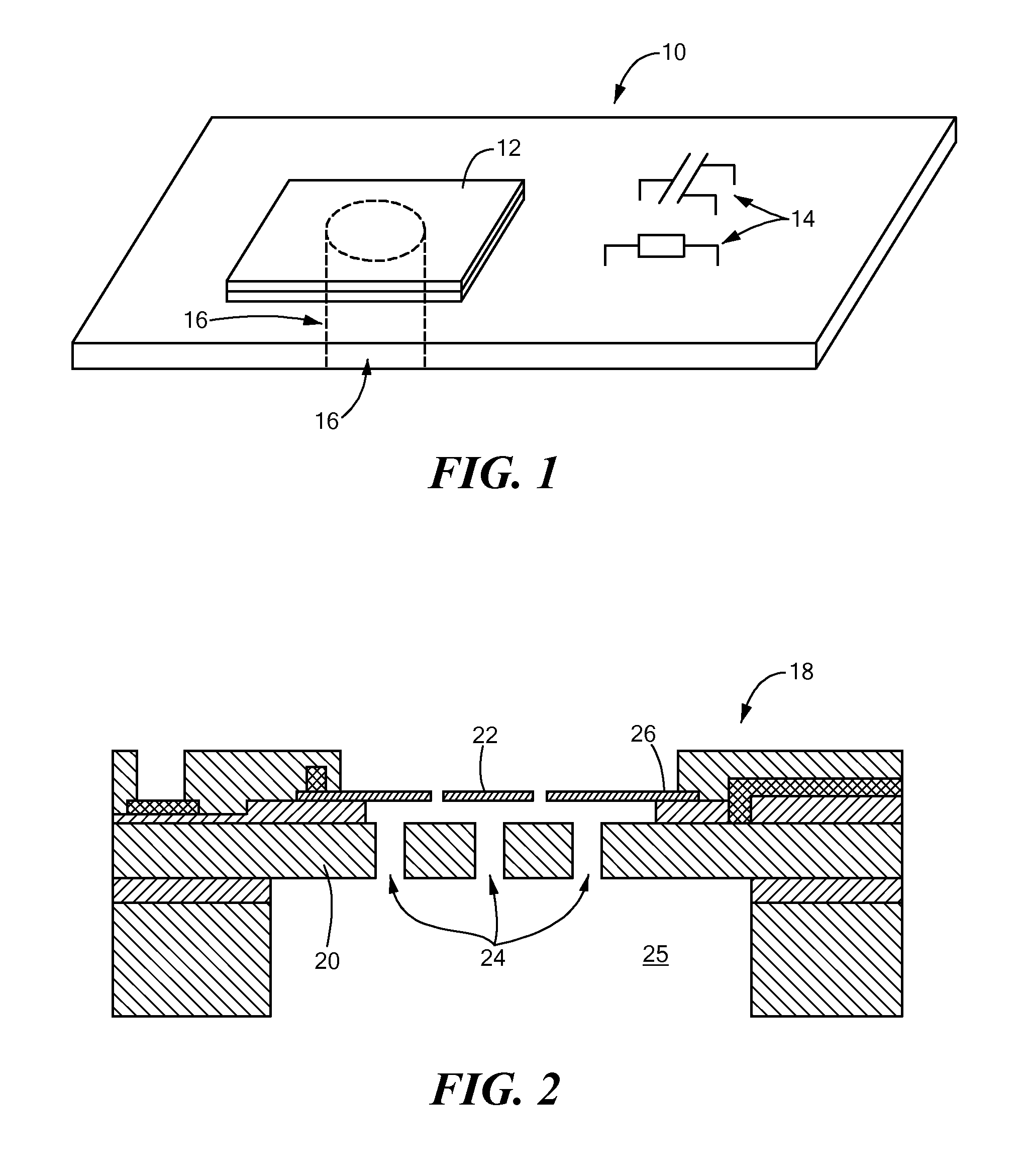
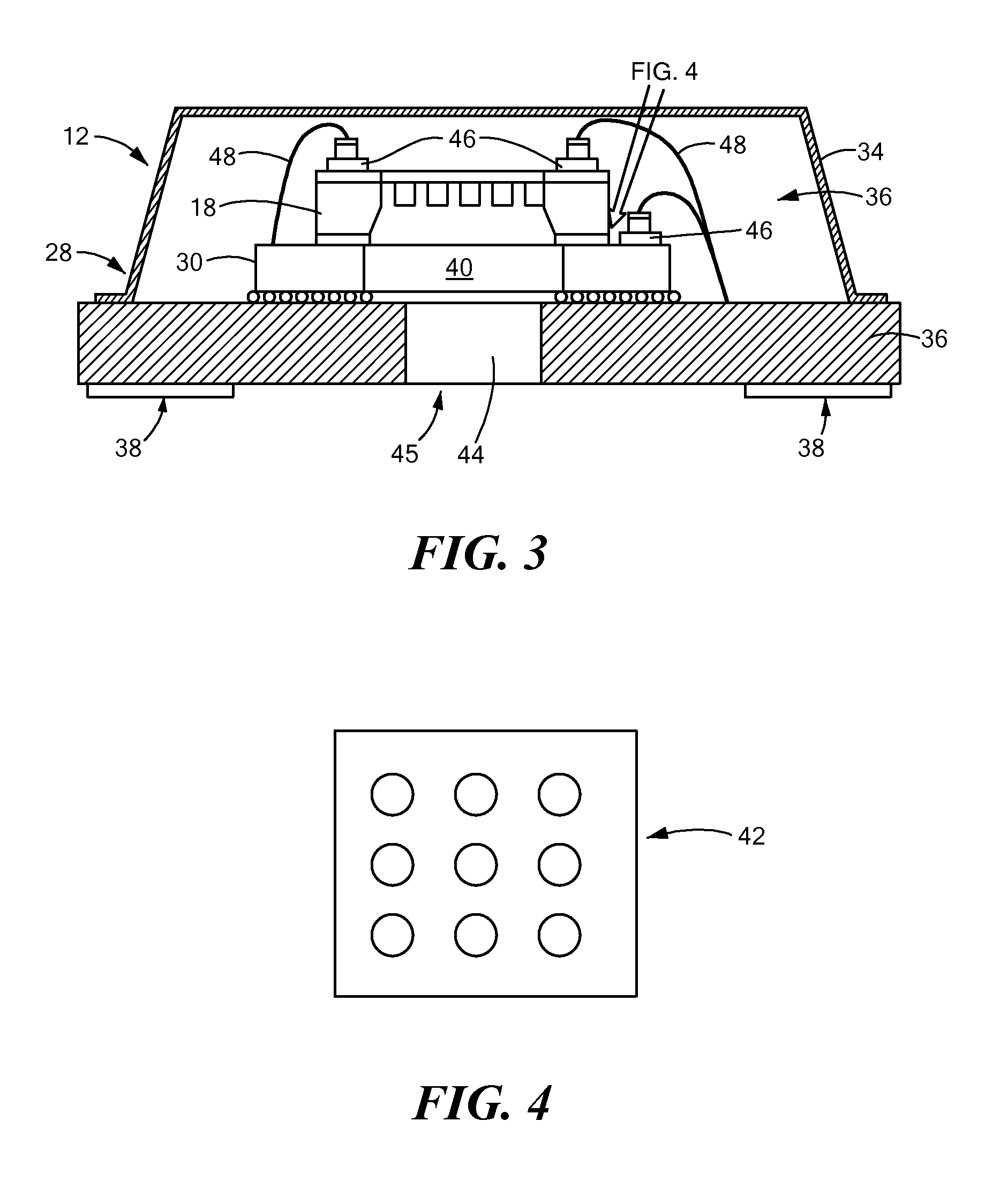
[0004]In accordance with one embodiment of the invention, a microphone system has a chip system coupled to a base. Among other things, the chip system includes a microphone chip and a circuit chip, in a stacked relationship, configured to electrically communicate. The microphone chip has a diaphragm configured to move upon receipt of an incident audio signal, while the circuit chip has at least one through hole audibly coupled with the diaphragm of the microphone chip.

[0005]In one implementation, the circuit chip is secured to a surface of the base, while the microphone chip is secured to a surface of the circuit chip. In that case, the circuit chip may be positioned between the microphone chip and the base. Moreover, various embodiments can have one or more different types of filters to protect the microphone chip. For example, the through hole of the circuit chip may include a plurality of holes that act as a filter. In addition, the assembly may have a filter, between the circuit...


PUM


Abstract

A microphone system has a chip system coupled to a base. Among other things, the chip system includes a microphone chip and a circuit chip, in a stacked relationship, configured to electrically communicate. The microphone chip has a diaphragm configured to move upon receipt of an incident audio signal, while the circuit chip has at least one through hole audibly coupled with the diaphragm of the microphone chip.

Description

TECHNICAL FIELD[0001]The invention generally relates to microchips and, more particularly, the invention relates to transducer chips.BACKGROUND ART[0002]MEMS microphones typically are housed within a package interior and controlled by an adjacent integrated circuit chip. The package thus must have a footprint that is large enough to hold both the microphone chip and the integrated circuit chip. In addition, MEMS devices, such as MEMS microphones chips, often have extremely clean microstructure surfaces. Such clean microstructure surfaces, however, can stick together if they come into contact. When the surfaces remain stuck together, the device often is inoperable. This concept of surface sticking is known in the art as “stiction.”[0003]A number of different factors can contribute to or cause stiction. For example, among other things, stiction may occur during wet release of a movable MEMS microstructure, where the surface tension of a draining rinse liquid can draw the microstructur...

Claims


Application Information

Patent Timeline
Patent Type & Authority Applications(United States)
IPC IPC(8): H04R25/00
CPCH04R1/04H04R19/005H01L2224/48091H01L2924/3025H01L2924/1461H01L2924/00014H01L2924/00H04R31/006
Inventor GOIDA, THOMAS
Owner INVENSENSE
Why Eureka
Try Eureka