
Mounting and dismounting device for cylindrical bodies

a technology of mounting and dismounting devices, which is applied in the direction of wrenches, screwdrivers, manufacturing tools, etc., can solve the problems of inconvenient carrying and operating of users, and becomes a difficulty in mounting or dismounting the cylindrical body, so as to facilitate the mounting and dismounting of the cylindrical body and achieve the effect of smoother and easier operation

Inactive Publication Date: 2012-02-09
MUELLER KUEPS
View PDF7 Cites 8 Cited by
  • Summary
  • Abstract
  • Description
  • Claims
  • Application Information

AI Technical Summary

Benefits of technology

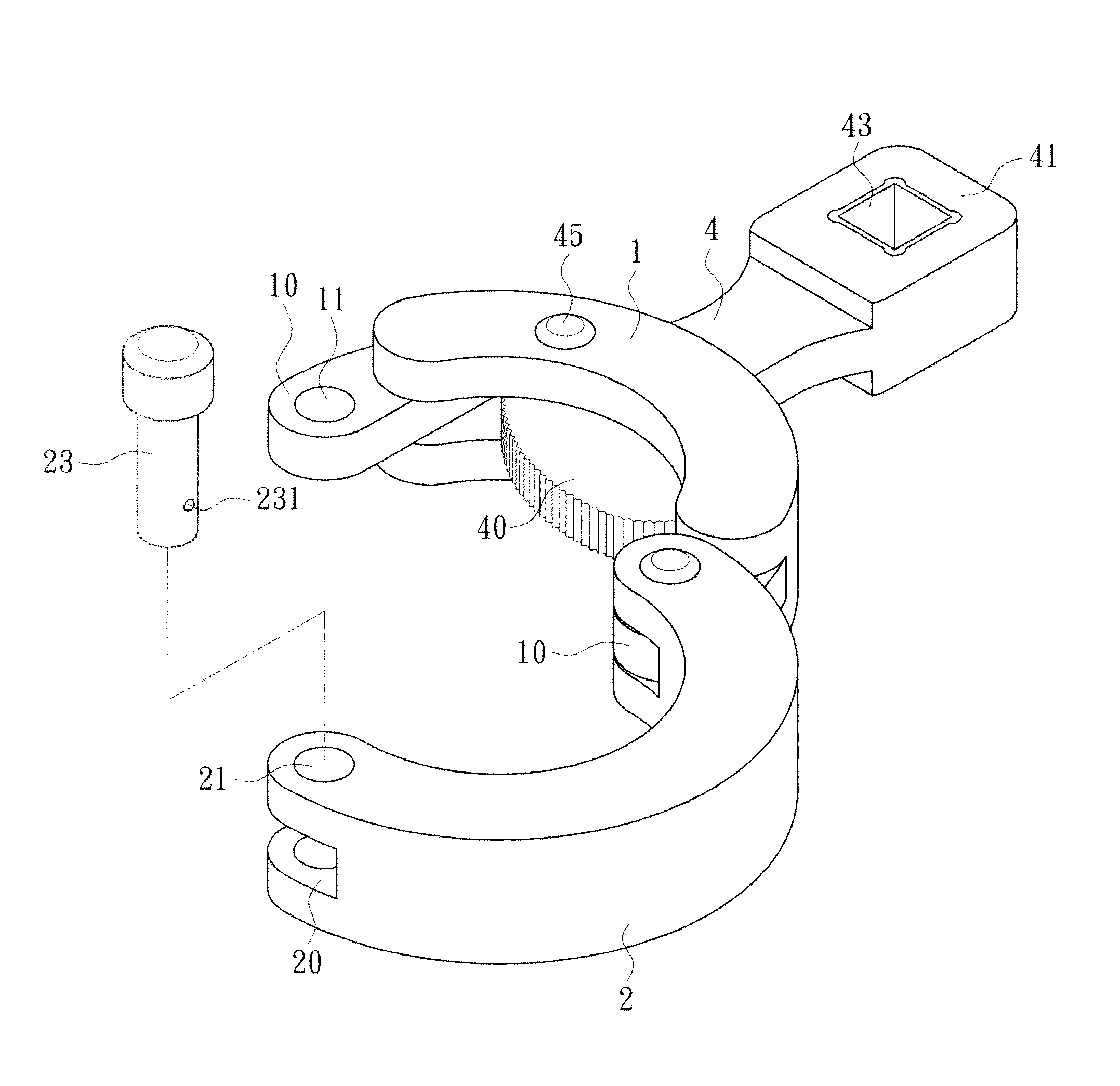
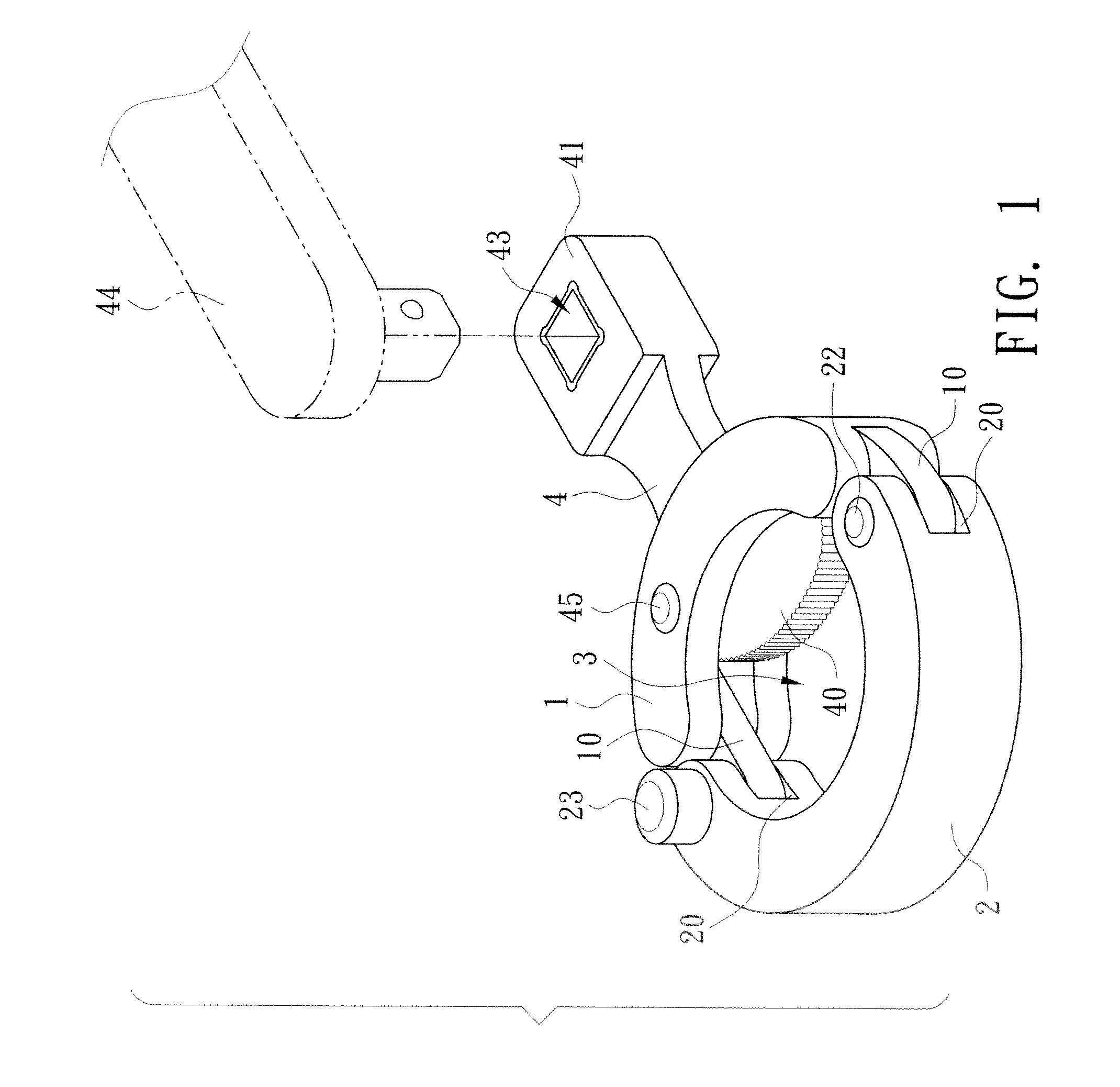
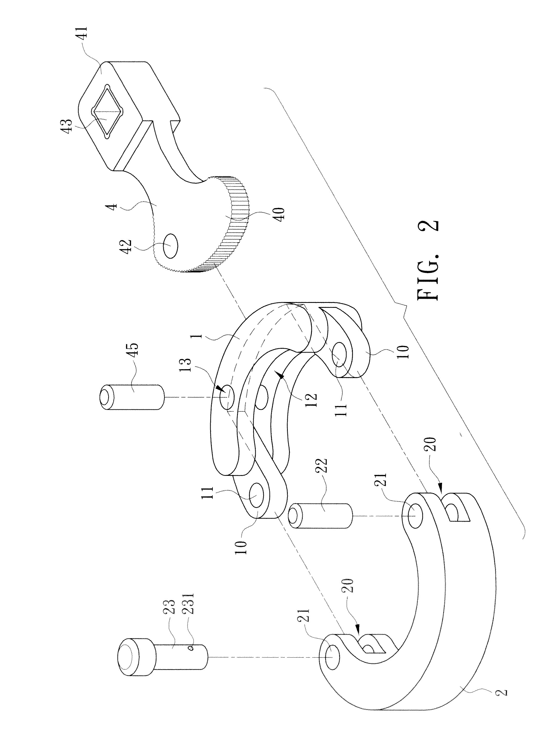
"The invention is a mounting and dismounting device for cylindrical bodies of different diameters. It includes a fixing element, a moving element, and a buckling element. The fixing element is a semicircular shape with protruding parts that have through holes and a horizontal groove. The moving element is also a semicircular shape with recess parts that can hold the protruding parts of the fixing element. The moving element has through holes connected to the fixing element. The buckling element is a cam-shaped part with a mounting hole for an auxiliary tool and a lifting part that can be urged against the cylindrical body. The device makes mounting and dismounting cylindrical bodies easier and smoother."

Problems solved by technology

This is quite inconvenient for users to carry and operate.
This becomes a difficulty for mounting or dismounting the cylindrical body 93.

Method used


Image

  • Mounting and dismounting device for cylindrical bodies
  • Mounting and dismounting device for cylindrical bodies
  • Mounting and dismounting device for cylindrical bodies

Examples


first embodiment

[0028]FIGS. 4 and 5 show the actual operations of the disclosed mounting and dismounting device in the There are a cylindrical body 5 and a cylindrical body 6 in FIGS. 4 and 5, respectively. The diameter of the cylindrical body 5 in FIG. 4 is apparently smaller than that of the cylindrical body 6 in FIG. 5. After inserting the CB5 and the cylindrical body 6 into the hole 3 of the disclosed mounting and dismounting device, one lifts the buckling element 4 for the buckling part 40 to extend into the hole 3. The depth of the buckling part 40 into the hole 3 is adjusted according to the size of the cylindrical body 5 or cylindrical body 6. One is thus able to mount and dismount the cylindrical body 5 and the cylindrical body 6 in the same way.

[0029]According to the above description, it is apparent that the primary features of the invention is in that the fixing element 1 and the moving element 2 can be connected or disconnected with the positioning axis 23. If the open end of the cyli...

second embodiment

[0030]Of course, the invention has many other embodiments that only differ from the above one in details. FIG. 6 shows the invention. The fixing element 1 is still an integrally formed block structure. The moving element 2A is now a chain. As shown in the drawing, the cylindrical body 7 has an elliptical shape. Since the chain as the moving element 2A can change its length, the cylindrical body of such a shape can still be urged, thereby mounted or dismounted.


PUM


Abstract

A mounting and dismounting device for cylindrical bodies comprises a fixing element, a moving element, and a buckling element. The fixing element connects to the moving element on both sides to form a hole. The cylindrical body is then inserted into the hole. A buckling part of the buckling element pivotally connects to the fixing element. One lifts a lifting part for the buckling element to urge against the cylindrical body in the hole. By lifting the lifting part, the cylindrical body can be mounted or dismounted.

Description

BACKGROUND OF THE INVENTION[0001]1. Field of Invention[0002]The invention relates to a mounting and dismounting tool and, in particular, to a mounting and dismounting device for cylindrical bodies.[0003]2. Related Art[0004]FIG. 7 shows a conventional mounting and dismounting device. It consists of a hollow ring 90 and a buckling element 91. The buckling element 91 is pivotally provided to the side of the ring 90. One end of the buckling element 91 has a buckling part 92 that extends into the ring 90. The ring 90 is then mounted on a cylindrical body 93. The buckling element 91 is rotated to urge against the cylindrical body 93. This mechanism is used to mount or dismount the cylindrical body 93.[0005]However, the above-mentioned mounting and dismounting device for cylindrical bodies has to have the right size for the cylindrical body in order to work. If there are cylindrical bodies of two or more different sizes, then different mounting and dismounting devices are required. This is...

Claims


Application Information

Patent Timeline
Patent Type & Authority Applications(United States)
IPC IPC(8): B25B13/50B25B13/34
CPCB25B13/50B25B13/52B25B13/505
Inventor MUELLER, MICHAEL
Owner MUELLER KUEPS
Learn More