
Portable work light clamp

a work light and clamping technology, applied in the field of work lights, can solve the problems of not being able to selectively and easily position and secure the work light for more unique or specialized applications, and the prior art lamp is often not designed to be selectively and easily positioned and secured

Inactive Publication Date: 2012-02-09
IBT HLDG
View PDF13 Cites 34 Cited by
  • Summary
  • Abstract
  • Description
  • Claims
  • Application Information

AI Technical Summary

Benefits of technology

"The patent describes a portable work light clamp system that allows for easy and adjustable positioning of a light for use in construction or other activities. The system includes two clamps that can be used together or separately, and a light assembly that can be adjusted in different directions. The system also includes a slotted extension member that allows for easy movement of the light base along its length. The technical effects of this invention include improved flexibility, adjustability, and versatility in lighting construction projects."

Problems solved by technology

However, many times an individual user of a handheld light may need to operate another tool in the space illuminated by a handheld light.
Despite their relative ease of use, the prior art lamps are often not designed to be selectively and easily positioned and secured for more unique or specialized applications.

Method used


Image

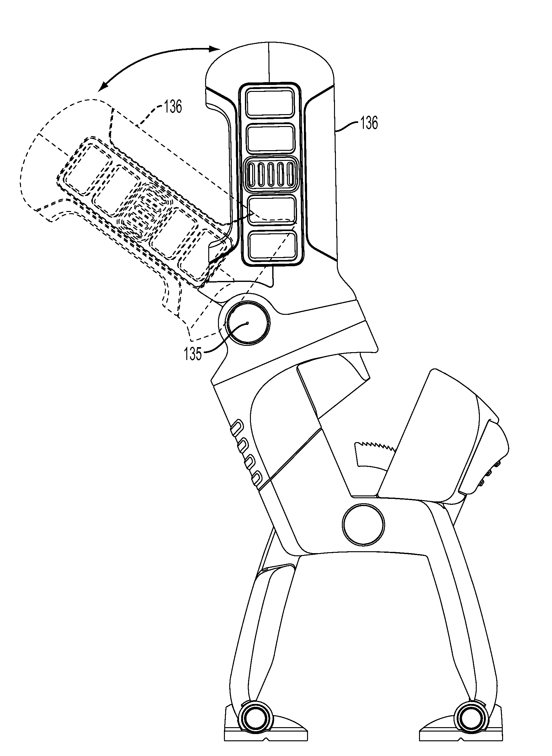
  • Portable work light clamp
  • Portable work light clamp
  • Portable work light clamp

Examples


Embodiment Construction

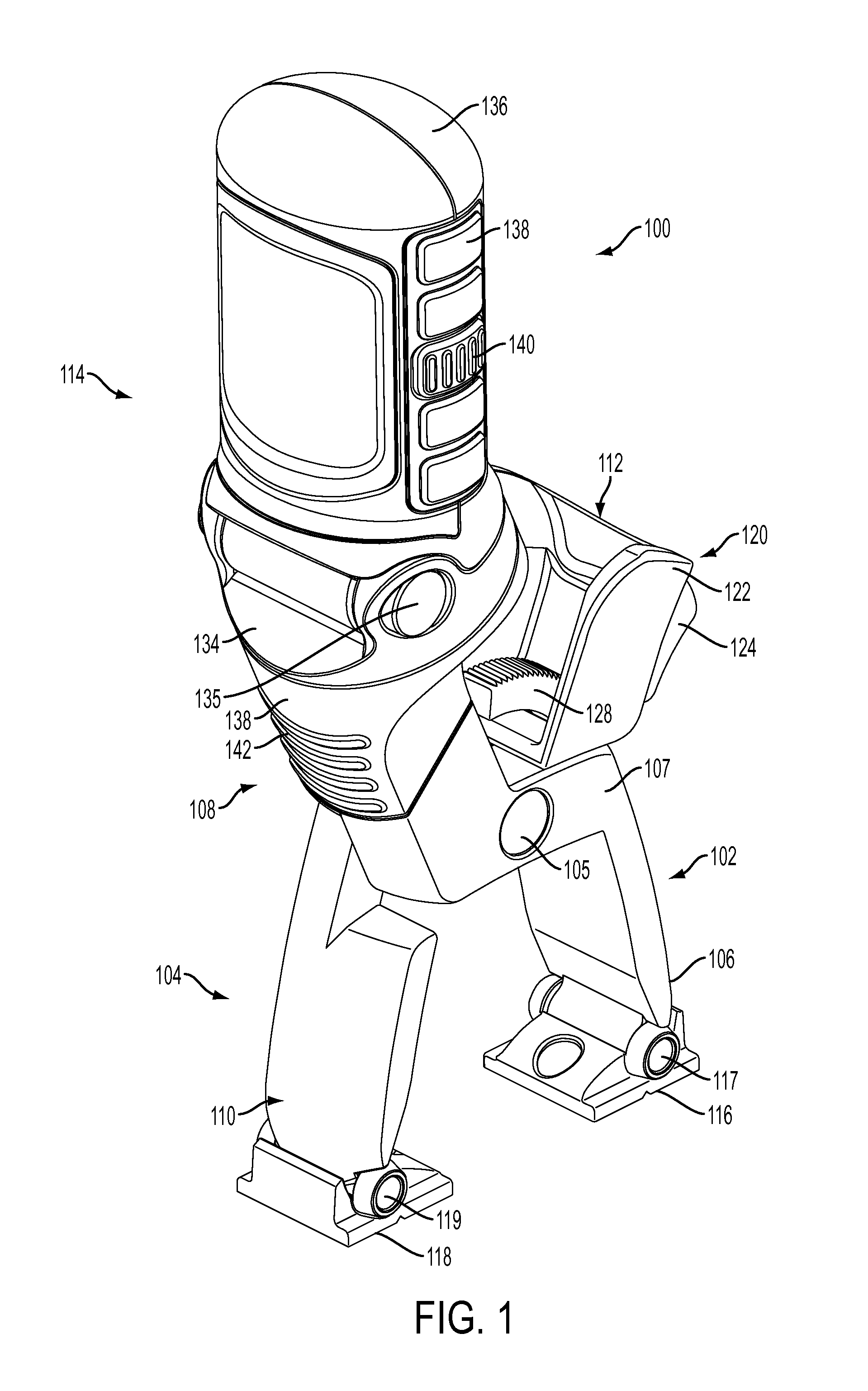
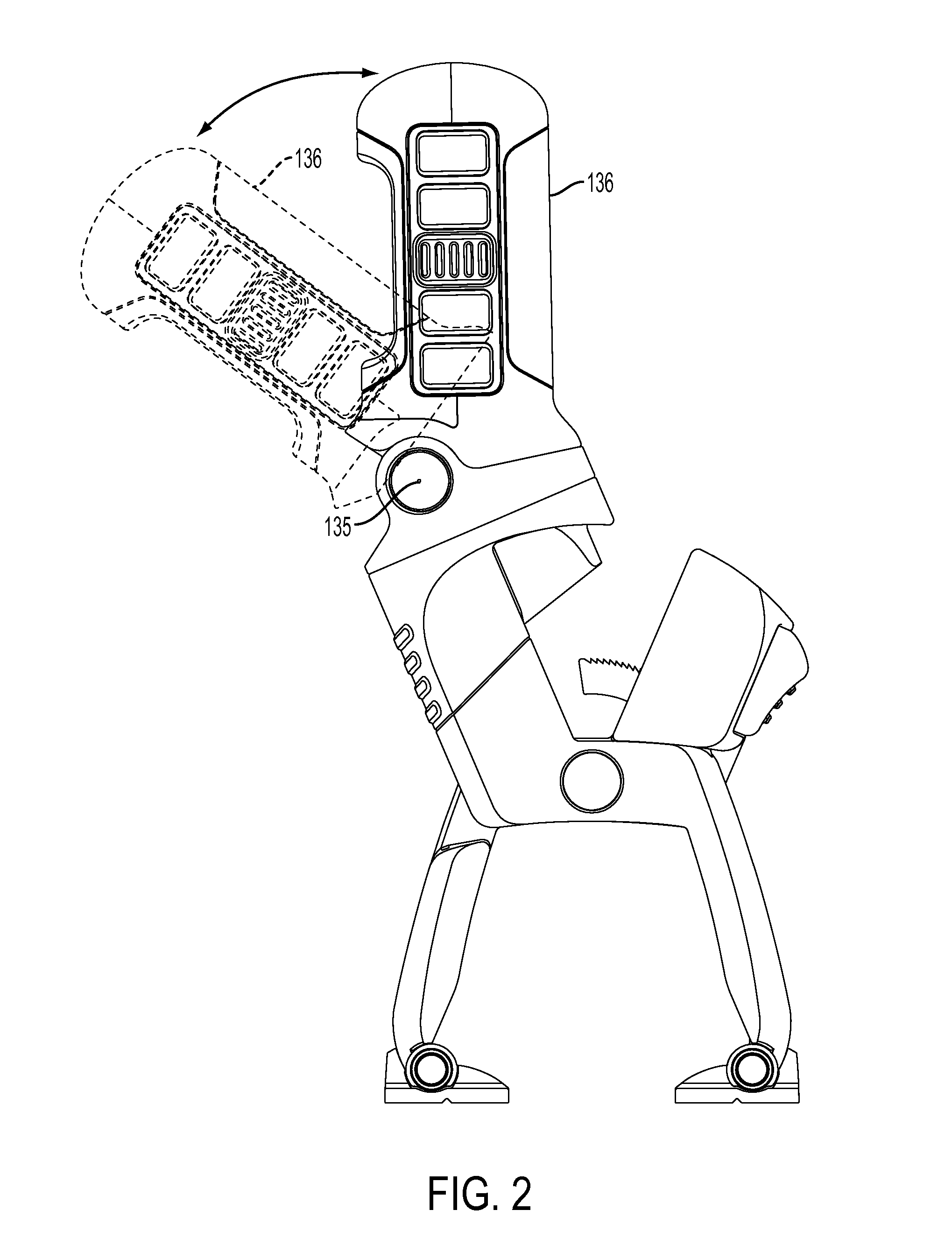
[0014]FIGS. 1-4 illustrate an exemplar work light clamp system 100. The work light clamp system 100 includes a first clamp handle assembly 102 and a second clamp handle assembly 104 pivotally connected by a clamp pivot 105 (e.g., roll pin, bolt, rivet, screw and the like) for pivotal opposed operation (e.g., scissors-like motion). First clamp handle assembly 102 can include a proximal end 106, a mid section 107 and a distal end 108. The proximal end 106 can include a standing / gripping member 116 that is pivotally coupled thereto by jaw pivot 117. Standing / gripping member 116 can be rotated for standing on a work surface as illustrated in FIG. 1. Alternately, as illustrated in FIG. 3, standing / gripping member 116 can be rotated for clamping to a work surface. Mid section 107 includes a clamp bar 128 that forms part of locking assembly 120, which will be discussed in greater detail below. Distal end 108 can include a light assembly 114. Light assembly 114 can include a light housing 1...


PUM


Abstract

A portable work light clamp system includes a first clamp handle assembly having a proximal end, a mid section and a distal end and a gripping member rotatably coupled to the proximal end of the first clamp handle assembly. The work light clamp system further includes a second clamp handle assembly having a proximal end and a distal end and a gripping member rotatably coupled to the proximal end of the second clamp handle assembly. The first clamp handle assembly and the second clamp handle assembly pivotally connected by a clamp pivot for pivotal opposed operation. A light assembly is coupled to the distal end of the first clamp handle assembly. The light assembly includes a swivel base member and a light housing pivotally coupled to the swivel base member by a light pivot that enables the light housing to selectively pivot 50 degrees about a longitudinal axis of the light pivot. The light assembly further includes a light base coupled to the swivel base member and rotatable relative to the light base by a swivel connector that enables the swivel base member to selectively rotate 360 degrees around a longitudinal axis of the light base. The work light clamp further can include a slotted extension member having a length that is coupled to the distal end of the first clamp handle assembly and coupled to a light base by a connector that enables the light base member to slidably extend along the length of the slotted extension member.

Description

BACKGROUND OF THE INVENTION[0001]1. Field of the Invention[0002]The disclosure relates generally to work lights and, more specifically, to rotatable and adjustable work lights that can be clamped to, mounted to or placed on a surface.[0003]2. Description of the Related Art[0004]Handheld lights are common tools found in the everyday toolbox. However, many times an individual user of a handheld light may need to operate another tool in the space illuminated by a handheld light. Small portable lamp assemblies, especially those that employ quartz halogen lamps, are especially well suited for home use as well as for professional use that includes automotive repair shops, construction and excavation sites, photography studios and in various situations where a portable light source is required to illuminate specific objects and areas.[0005]Most portable lamp assemblies are equipped with either a handle for carrying or are mounted on a stand for stationary, long-term positioning. These lamp...

Claims


Application Information

Patent Timeline
Patent Type & Authority Applications(United States)
IPC IPC(8): B25B23/18
CPCF21L14/02F21V21/30F21V21/28F21V21/088
Inventor MOLINA, FRANCISCOROBINSON, GLENN
Owner IBT HLDG
Learn More