Handling maschine for rails and handling process associated thereto

a technology of handling machine and rail, which is applied in the direction of metal rolling arrangement, pile separation, lighting and heating apparatus, etc., can solve the problems of high energy consumption, low efficiency, and complex rail handling system, and achieve the effect of avoiding damage to the external surface of the rail and the handler, and facilitating the handling of the rail

Active Publication Date: 2012-02-09
DANIELI & C OFF MEC SPA
View PDF5 Cites 0 Cited by
  • Summary
  • Abstract
  • Description
  • Claims
  • Application Information

AI Technical Summary

Benefits of technology

[0014]It is the main object of the present invention to implement a handling machine for handling rails, arranged in line and immediately downstream of a rolling plant, which allows both to easily handle the rail for transferring it from the roller table to the thermal treatment zone, and to ens

Problems solved by technology

This implies the need to stock the rolled rails and subsequently heat them before proceeding with the thermal quenching treatment, with high energy consumption and low efficiency.
A first drawback of these solutions is the complexity of the rail handling systems which move the rail on the roller table along the thermal treatment plant.
In particular, if an immersion tank is used, cooling is more uniform lengthwise, but in all cases the temperature difference between the base of the hot rail and the cooled head results in the rail deflection or bending.
Therefore, a second drawback of the known solutions is that these variations of longitudinal profile of the rail, more accentuated at the ends, cause the exertion of high

Method used


Image

  • Handling maschine for rails and handling process associated thereto
  • Handling maschine for rails and handling process associated thereto
  • Handling maschine for rails and handling process associated thereto

Examples


first embodiment

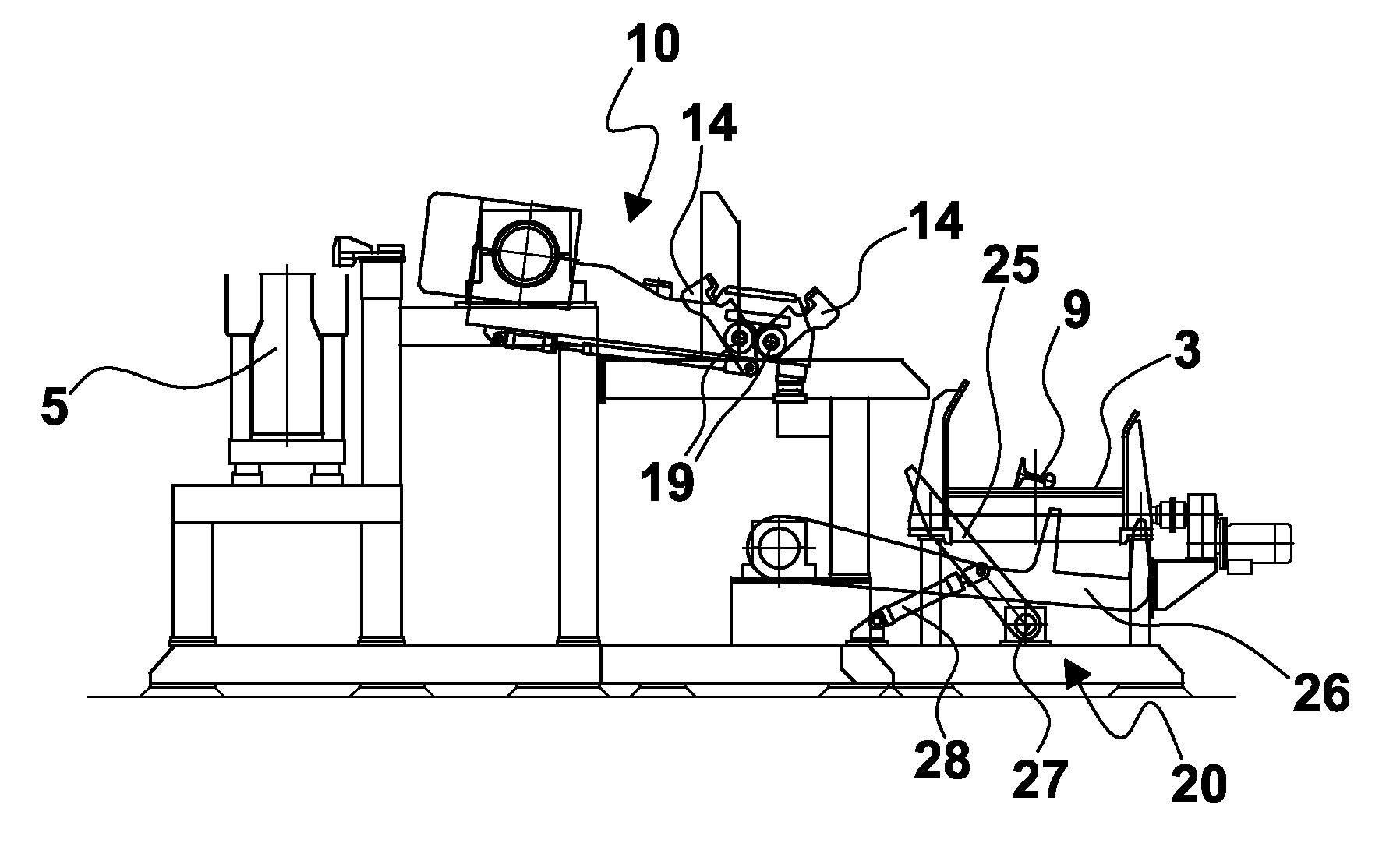
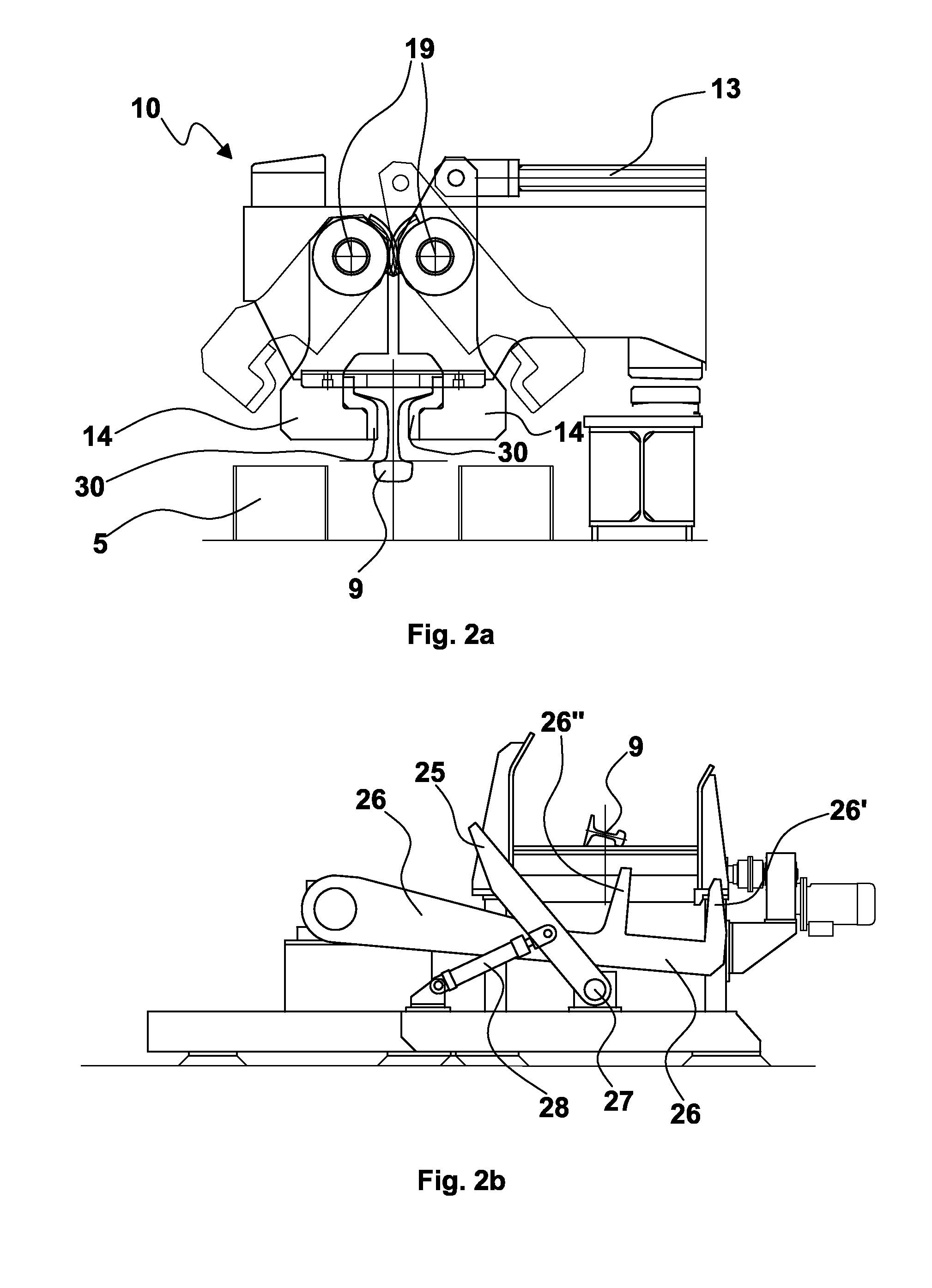
[0088]The transmission shafts 11 of the various modules are controlled by respective motors. Advantageously, if drive problems occur in any module of the plant, the shafts 11 are provided on one end with a connection element adapted to mesh with a respective recess provided on the proximal end of the subsequent shaft 11. The handling process of the rails, carried out by means of the aforesaid first embodiment of the handling machine, comprises the following steps:[0089]1) unloading a rail 9 in a lopsided position, that is inclined on a side thereof, onto the roller table 3; during this step of receiving the rail, pushers 25 and levers 26 are in the respective external resting positions and underneath the roller table 3 (FIG. 3);[0090]2) actuating the pushers 25 by means of the hydraulic cylinders 28 so as to turn them by a predetermined angle, e.g. about 30°, in a first direction of rotation about respective pins 27, moving the rail 9, inclined on a side thereof, laterally with resp...

second embodiment

[0143]The main advantage obtained by this second embodiment of the handling machine is represented by a production rate of 27-28 rails / hour and an hourly production rate of 180-200 tons / hour.


PUM

PropertyMeasurementUnit
Angleaaaaaaaaaa
Bending strengthaaaaaaaaaa

Abstract

A handling machine for rails, arranged in line and immediately downstream of a rolling plant, which allows both to easily handle the rail for transferring it from the roller table to the thermal treatment zone, and to ensure an optimal gripping of the rail along its longitudinal extension, thus effectively contrasting its bending and variations while allowing a longitudinal movement of the rail caused by thermal shrinkage, thus avoiding damages both to the external surface of the rail and to the handlers. A rail handling process is also described, which optimizes moving, positioning along a roller table and maintaining the rail substantially rectilinear during the thermal treatment to which it is subjected.

Description

FIELD OF THE INVENTION[0001]The present invention relates to a handling machine for rails, in particular to a machine suitable for handling at least one rail in a thermal treatment plant for rail heads, said thermal treatment plant being arranged in line and immediately downstream of a rolling plant, and further relates to a rail handling process associated thereto.STATE OF THE ART[0002]The prior art has various solutions of thermal treatment plants for rolled rails, particularly aimed at hardening the head by means of quenching operation. Many of these systems are not arranged immediately after the rolling train outlet. This implies the need to stock the rolled rails and subsequently heat them before proceeding with the thermal quenching treatment, with high energy consumption and low efficiency.[0003]In other solutions, instead, these systems are arranged downstream of the rolling mill: the rolled rail is unloaded onto a roller table fixed to the ground; it is then drawn by handle...

Claims


Application Information

Patent Timeline
IPC IPC(8): B21B39/20F28F7/00B25J11/00B21B39/22B21B39/24
CPCB21B1/085B21B39/24C21D2221/00C21D9/06C21D1/63
Inventor POLONI, ALFREDOSCHREIBER, MARCO
Owner DANIELI & C OFF MEC SPA
Why Eureka
Try Eureka