LED Lighting Device

a technology of led lighting and lighting support, which is applied in the direction of lighting support devices, light source combinations, and built-in power, etc., can solve the problems of inability to adjust the lighting effect in time, the lighting effect can be hit and broken by the people around the table, and the time consumed can become a huge logistic problem, etc., to achieve easy adjustment up and down, easy engagement, and easy to take

Inactive Publication Date: 2012-02-16
GENERAL LED AI HLDG LLC
View PDF3 Cites 15 Cited by
  • Summary
  • Abstract
  • Description
  • Claims
  • Application Information

AI Technical Summary

Benefits of technology

[0012]The above objects of the invention and advantages are achieved by having a central housing that will be able to accommodate one or more LED light sources. The housing will be easily engageable with the leg of the table such that it will move with the table. The engagement with the leg can be a hole in the middle of the housing through which the leg of the table will be insertable. With the use of a clamping device within the hole, the housing can be easily adjusted up and down to generate the desired lighting effect. For a table with a central column as the sole supporting leg of the table, engaging the housing with the table through this hole will ensure that the device is properly placed to create the desired lighting effect and that the device cannot be easily taken without disassembling the table. The use of LED lights will not generate as much heat as easily as other light sources would and it is also easier to implement different colors schemes.

Problems solved by technology

If the caterer has 100 tables on which to create this lighting effect, the time consumed can become a huge logistic problem.
In addition, as the lights are simply lying on the floor, there is a possibility that a light can be inadvertently shifted to change the lighting effect.
Another problem exists because the lights can be hit and broken by the people that are around the table.
Yet another problem occurs if the tables are subsequently moved, then the lights will also have to be moved.
Again, for a large number of tables, this will involve a lot of time.
While it is possible to use tape or other temporary fasteners to attach the lights to the table, that would increase the amount of time and labor that would be needed to setup each table in addition to adjusting each light under the table to achieve the desired effect.
Another problem can occur if incandescent or fluorescent bulbs are used in this fashion as the resultant heat from the bulbs can be undesireable to the people gathered around the table.

Method used


Image

  • LED Lighting Device
  • LED Lighting Device
  • LED Lighting Device

Examples


Embodiment Construction

[0024]For the purposes of understanding the invention, reference will now be made to the embodiments illustrated in the drawings. It will be understood that no limitation of the scope of the invention is thereby intended. Any alterations and further modifications in the described embodiments, and any further applications of the principles of the invention as described herein are contemplated as would normally occur to one skilled in the art to which the invention relates.

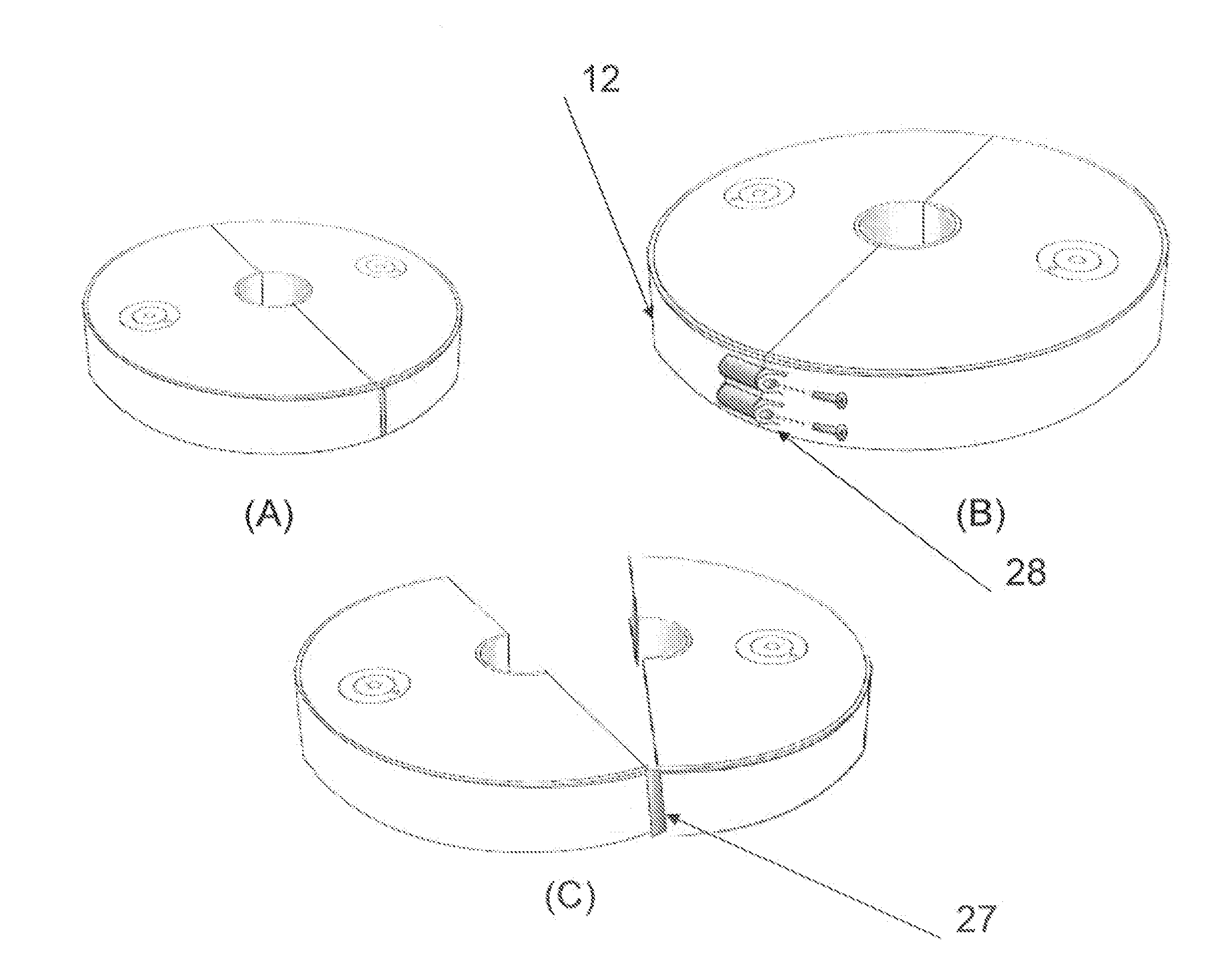
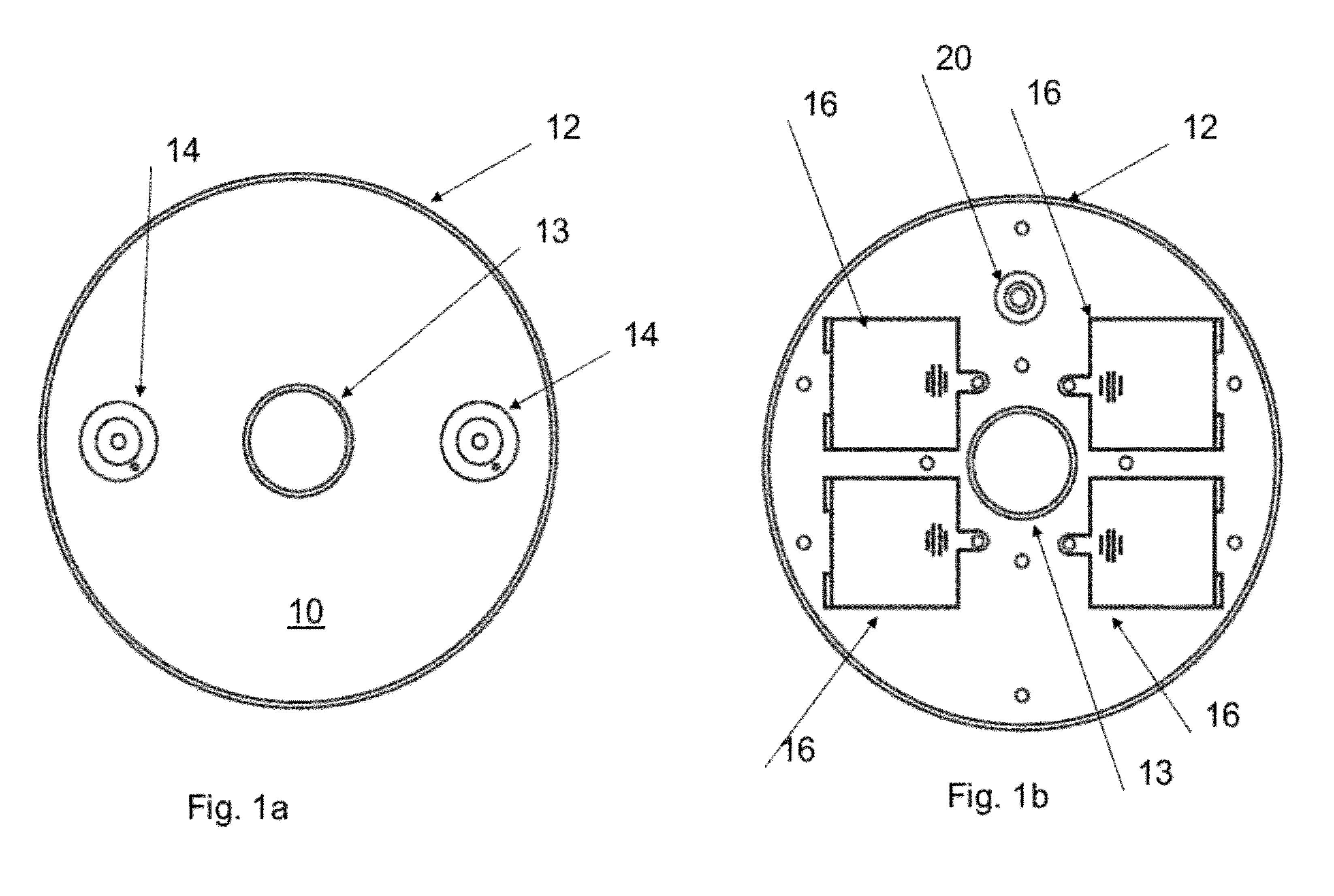
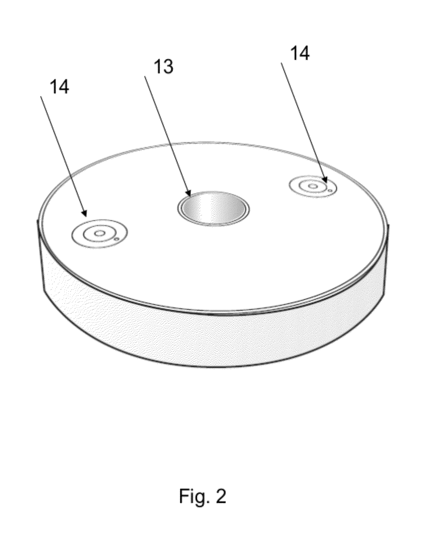
[0025]Referring to FIGS. 1a-b and 2, one embodiment of the invented LED device is depicted. The invented LED device 10 is composed of a circular housing 12 with a hole 13 that extends through the entire housing in the middle of the housing 12. The hole 13 can be of any size, but should be big enough to accommodate the standard width of a table leg. A typical table leg width can be approximately 22 mm and the hole 13 in the housing 12 should be large enough to accommodate any width of a table leg. A clamping device c...


PUM


Abstract

An LED lighting device is described that comprises of a housing. The housing is capable of engaging with a leg of a table via a hole in the center of the housing. The housing also contains a first LED light source, a power source to power said first LED light. The LED lighting device can also have a second or multiple LED lighting sources housed within the housing.

Description

CROSS-REFERENCE TO RELATED APPLICATIONS[0001]This application relates to and claims priority rights from provisional application U.S. 61 / 338,164 filed on Feb. 16, 2010, the entire disclosures of which are hereby incorporated by reference herein.BACKGROUND OF THE INVENTION[0002]1. Field of the invention[0003]This invention relates to an apparatus for providing decorative LED based light.[0004]2. Description of the Related Art[0005]Lighting can often be used as a decorative tool. A lighting scheme will create a visual image that can be used to set an atmosphere of a room. Finding the right lighting device to achieve the desired visual effect can depend greatly on the particular circumstances of the situation. The location of the light source, the direction of where the light is to be shone, the colors of the light, the powering of the light source and the portability of light source are all considerations in implementing a lighting scheme.[0006]One popular decorative lighting techniqu...

Claims


Application Information

Patent Timeline
Patent Type & Authority Applications(United States)
IPC IPC(8): H05B37/02F21V5/04F21V7/00F21V15/00F21V21/00
CPCF21S9/02F21V15/01F21V21/088F21V21/116F21V23/0435F21W2131/301F21Y2115/10F21Y2113/13
Inventor GUERRIERI, SALVATOREHAMEL, STEVEN
Owner GENERAL LED AI HLDG LLC
Why Eureka
Try Eureka