Swivel Screw Ligament Fixation Device

Inactive Publication Date: 2012-02-16
WALKER PETER MICHAEL SUTHERLAND
View PDF9 Cites 91 Cited by
  • Summary
  • Abstract
  • Description
  • Claims
  • Application Information

AI Technical Summary

Benefits of technology

[0033]Preferably a screw fastener can be located within a tunnel (or hole) formed in a bone and rotatably coupled to a graft, wherein rotation of the screw fastener with respect to the bone pulls the graft though the tunnel. More preferably, rotation of screw fa

Problems solved by technology

Therefore, this tension device can not fine tune or adjust the te

Method used


Image

  • Swivel Screw Ligament Fixation Device
  • Swivel Screw Ligament Fixation Device
  • Swivel Screw Ligament Fixation Device

Examples


Example

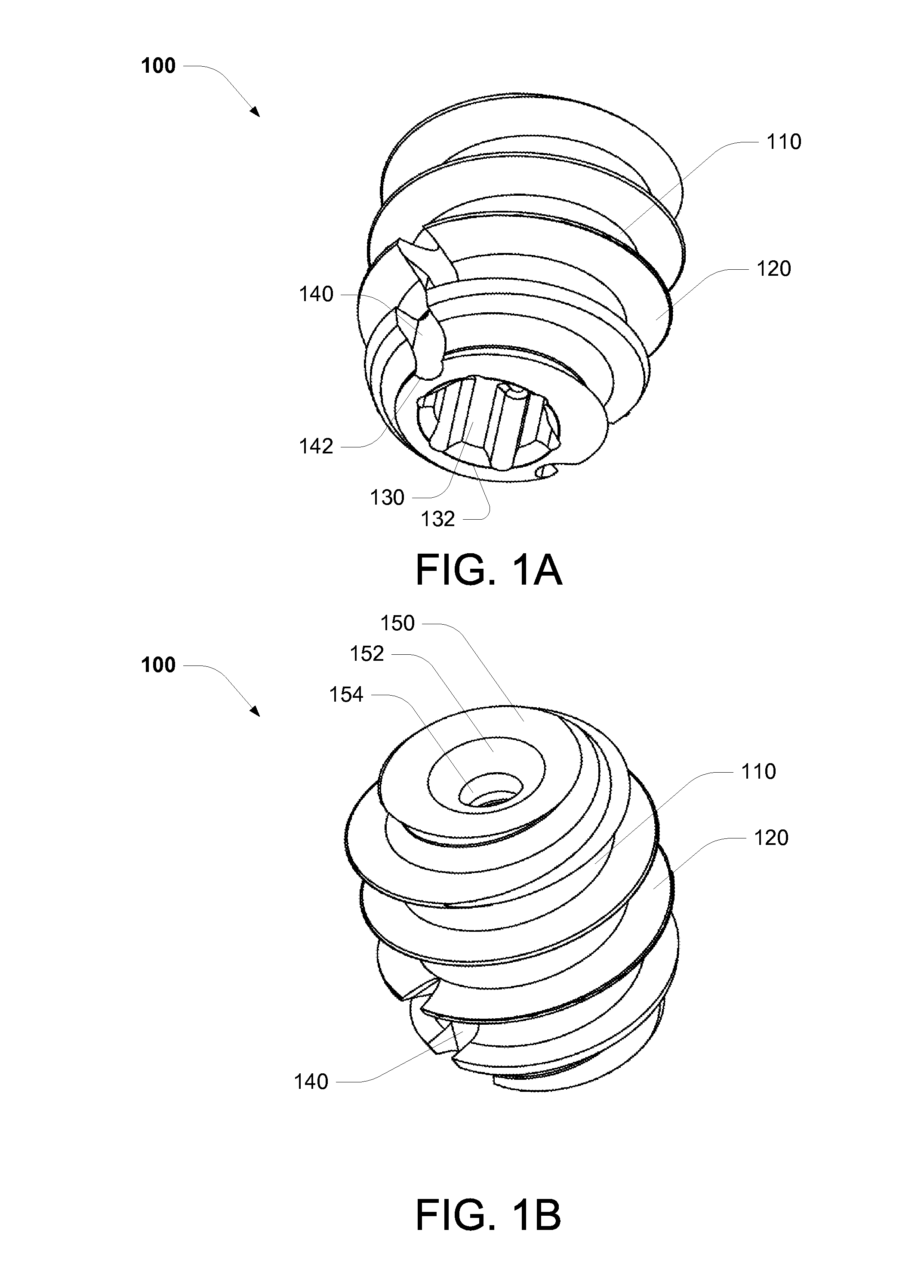
[0070]As shown in FIG. 1A, a fastener 100, in accordance with the teachings of the present invention, comprises a relatively coarse threaded slightly tapered plug (or body) 110 having the fastening characteristics of a bone screw. External screw threads 120 are adapted to be self tapping into a tunnel pre-drilled through the tibia or femur. A central longitudinal bore or passageway 130 extends through the fastener, from one end to the other.

[0071]By way of example, a device of this kind will typically be about 6 mm to 14 mm in diameter and have a length of about 15 mm to 20 mm.

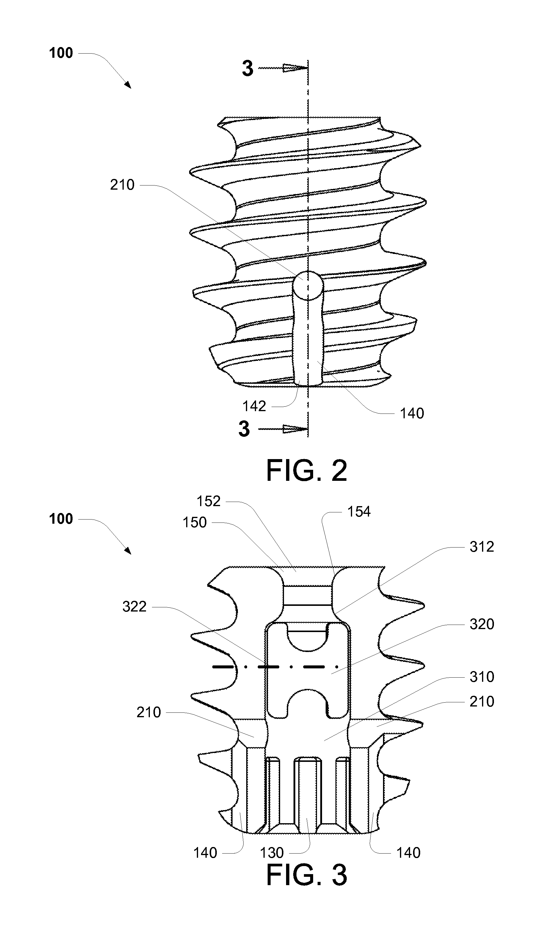
[0072]In an embodiment, a proximal end of the passageway 132 forms a socket for receiving a driver (including a adaptor and / or tool) such as a Torx brand driver. It will be appreciated that the socket, and therefore the head of a corresponding driver, can comprise numerous configurations, including a hex socket, and / or a star socket. A driver is adapted to accommodate the socket configuration.

[0073]Opposing lo...


PUM


Abstract

A surgical screw fastener device and method for pulling a graft through a first tunnel defined in a first bone. The surgical screw fastener including a body having a proximal end and a distal end, and an exterior screw thread located around the body for threadedly engaging a wall of the first tunnel. The device can have a first coupling element at the proximal end of the body, wherein the first coupling element adapted to couple a driver tool. The device can further have a second coupling element for rotatable coupling of a first end of the graft with respect to the device.

Description

FIELD OF THE INVENTION[0001]The present invention relates to fastening devices and in particular to screw fastening devices.[0002]The invention has been developed primarily for use as a fastener that can be used from within a bone tunnel to pull a graft (including tendons or ligament) though a tunnel (or hole) in a bone and will be described hereinafter with reference to this application. However, it will be appreciated that the invention is not limited to this particular field of use.BACKGROUND OF THE INVENTION[0003]Any discussion of the prior art throughout the specification should in no way be considered as an admission that such prior art is widely known or forms part of the common general knowledge in the field.[0004]The present disclosure will be used with reference to an anterior cruciate ligament (“ACL”) reconstruction, but it will be understood that the technology and methods of the present invention may have other applications.[0005]The ACL reconstruction can be done in nu...

Claims


Application Information

Patent Timeline
IPC IPC(8): A61B17/86
CPCA61F2/0805A61F2/0811A61F2002/0882A61F2002/0841A61F2002/0852A61F2002/0829
Inventor WALKER, PETER MICHAEL SUTHERLAND
Owner WALKER PETER MICHAEL SUTHERLAND
Why Eureka
Try Eureka