Ophtalmic apparatus
a technology of ophtalmoscope and ophthalmoscope, which is applied in the field of ophthalmoscope, can solve the problems of poor operability, heavy burden on the operator, and large force on the mechanical system
- Summary
- Abstract
- Description
- Claims
- Application Information
AI Technical Summary
Benefits of technology
Problems solved by technology
Method used
Image
Examples
first embodiment
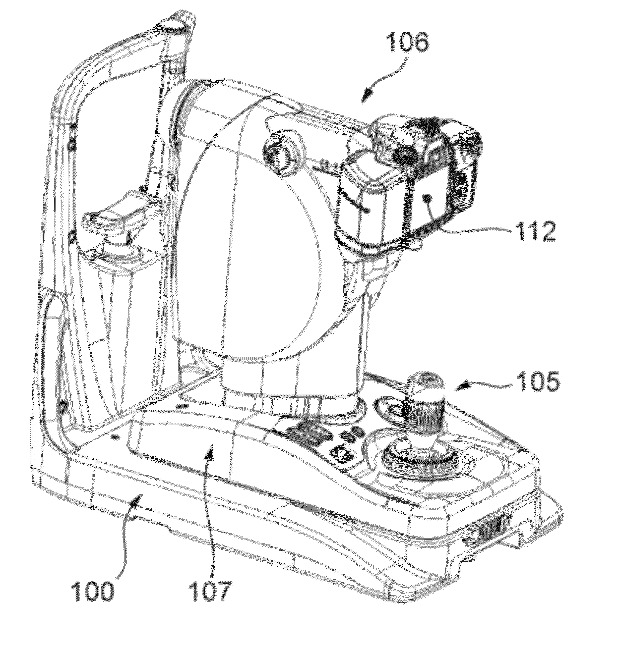
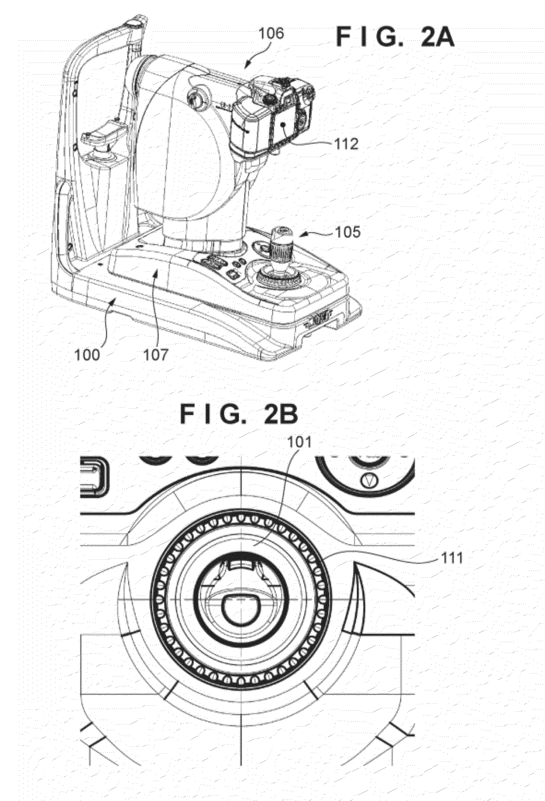
[0024]The schematic arrangement of a fundus shooting apparatus according to the first embodiment will be described with reference to FIGS. 1A to 3.
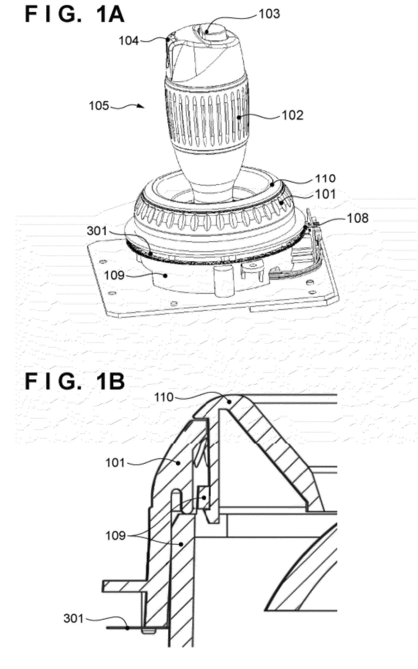
[0025]A joystick portion 105 that constitutes the joystick mechanism of the fundus shooting apparatus will now be described first with reference to FIG. 1A. The joystick portion 105 includes a focus dial 101 (a second rotary dial serving as a second rotary member) and a vertical movement dial 102 (a first rotary dial serving as a first rotary member). The joystick portion 105 also includes a shooting button 103, an anterior alignment switching button 104, a photo interrupter 108, a focus dial base portion 109, a locking member 110, and a slit plate 301 whose details are illustrated in FIG. 3.
[0026]The operator rotates the focus dial 101 to adjust the focus of the electric focusing mechanism that is the operation target. The focus dial 101 is arranged on the focus dial base portion 109 (supporting member) that supports the rotary dial. The...
second embodiment
[0052]The second embodiment is different from the first embodiment only in the arrangement of the focus dial and the optical vertical movement dial on the joystick, and the control method of the system control unit. Hence, mainly the different points will now be described with reference to FIGS. 6 to 9.
[0053]A joystick portion 605 according to the second embodiment will be described with reference to FIG. 6. The joystick portion 605 includes a shooting button 601, an anterior alignment switching button 602, an optical vertical movement dial 603, a focus dial 604, a top cover 606, a lower cover 607, and a dial strut 705 that is also illustrated in FIG. 7.
[0054]The optical vertical movement dial 603 has the same function as that of the vertical movement dial 102 described in the first embodiment. The optical vertical movement dial 603 pivots almost coaxially with the joystick portion 605. The optical vertical movement dial 603 has an almost hollow cylindrical shape and is pivotally fi...
third embodiment
[0066]The third embodiment is different from the first embodiment only in the arrangement of the focus dial and the optical vertical movement dial on the joystick, and the control method of the system control unit. Hence, mainly the different points will be described with reference to FIGS. 10 to 12.
[0067]A joystick portion 1003 according to the third embodiment will now be described with reference to FIG. 10. A rotary dial 1001 is mechanically linked with a slit plate 1102b of an encoder unit 1102 whose details are illustrated in FIG. 11, and rotates almost coaxially with the central axis of the joystick portion 1003. A switch 1002 changes the mode of the rotary dial 1001. The voltage of a mode switch 1103 shown in FIG. 11 changes upon flipping the switch 1002. A hole 1004 is formed to make the joystick portion 1003 project from the outer cover. In this embodiment, one rotary dial 1001 is arranged. However, a plurality of rotary dials may be arranged, and an operation target may be...
PUM
 Abstract
Description
Claims
Application Information
 - R&D
- Intellectual Property
- Life Sciences
- Materials
- Tech Scout
- Unparalleled Data Quality
- Higher Quality Content
- 60% Fewer Hallucinations
Browse by: Latest US Patents, China's latest patents, Technical Efficacy Thesaurus, Application Domain, Technology Topic, Popular Technical Reports.
© 2025 PatSnap. All rights reserved.Legal|Privacy policy|Modern Slavery Act Transparency Statement|Sitemap|About US| Contact US: help@patsnap.com


