High-frequency treatment tool

Active Publication Date: 2012-03-08
OLYMPUS CORP
View PDF3 Cites 2 Cited by
  • Summary
  • Abstract
  • Description
  • Claims
  • Application Information

AI Technical Summary

Benefits of technology

[0012]The high-frequency treatment tool according to the invention can be manufactured easily and

Problems solved by technology

When a short occurs, treatment canno

Method used


Image

  • High-frequency treatment tool
  • High-frequency treatment tool
  • High-frequency treatment tool

Examples


Example

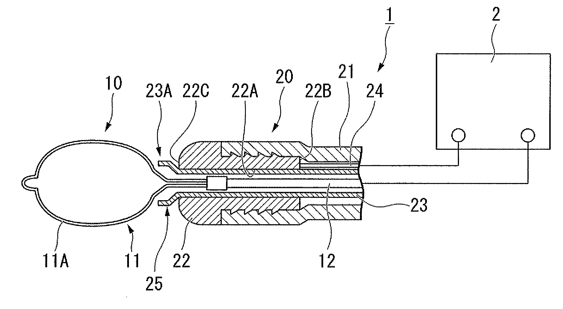
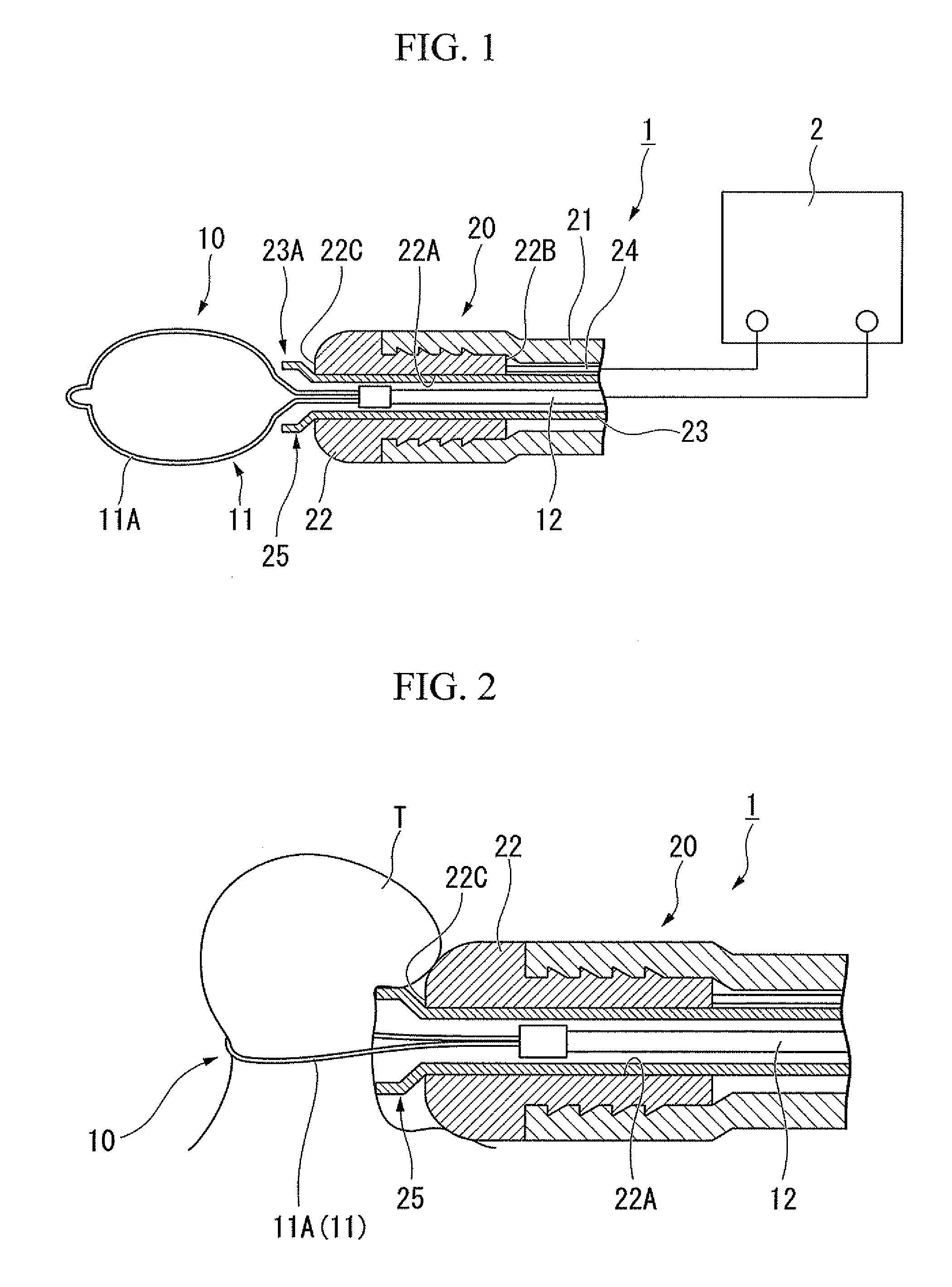
[0028]A high-frequency treatment tool according to a first embodiment of the invention will be explained with reference to FIG. 1 to FIG. 4B.

[0029]FIG. 1 is a diagram of the configuration of a high-frequency treatment tool 1 according to this embodiment. The high-frequency treatment tool 1 is a bipolar treatment tool used by inserting it into the forceps channel of an endoscope. The high-frequency treatment tool 1 includes a flexible elongated insertion part, a treatment part that is inserted into the insertion part such that it can be protruded from and receded into it, and an operation part that is connected to a proximal end of the insertion part and used in operating the treatment part.

[0030]FIG. 1 mainly illustrates the treatment part 10 and the distal-end part of the insertion part 20, and omits other parts of the insertion part 20, the operation part, and such like. The other parts of the insertion part 20, the operation part, and such like can be selected as appropriate from...

Example

[0047]Subsequently, a second embodiment of the invention will be explained with reference to FIG. 5. A high-frequency treatment tool 31 of this embodiment differs from the high-frequency treatment tool 1 of the first embodiment in regard to the configuration of the engagement part. In the following explanation, configurative elements that are common to the embodiments already mentioned are designated with same reference numerals and are not repetitiously explained.

[0048]FIG. 5 is a partial cross-sectional diagram of a distal-end part of the high-frequency treatment tool 31. As shown in FIG. 5, a ring-shaped diameter-expanding member (shape-preserving member) 32 has an outer diameter larger than the inner diameter of the inner tube 23, and is pressed into the distal-end part 23A of the inner tube 23, thereby forming a large-diameter part 33.

[0049]While there are no particular restrictions on the material for the diameter-expanding member 32, it must be rigid enough to keep the large-...

Example

[0053]Subsequently, a third embodiment of the invention will be explained with reference to FIG. 6. A high-frequency treatment tool 41 of this embodiment differs from the high-frequency treatment tools of the embodiments described above in regard to the configuration of the insertion part.

[0054]FIG. 6 is a cross-sectional diagram of the distal-end part of the high-frequency treatment tool 41. As shown in FIG. 6, the high-frequency treatment tool 41 includes an insertion part 50 instead of the insertion part 20. The insertion part 50 includes an outer tube 51 and an inner tube 23.

[0055]The outer tube 51 includes an outer-side tube main body 52 having insulating properties, and a tubular blade 53 disposed in an inner cavity of the tube main body 52. The blade 53 has a publicly known configuration woven from a plurality of metal wires. The inner tube 23 is inserted so as to cover the inner peripheral face of the tubular blade 53.

[0056]One part of the blade 53 protrudes from at the dist...


PUM


Abstract

A high-frequency treatment tool (1) includes an operating wire (12) having a treatment part (10) including a treatment electrode; a first tube (23) formed from an insulating material, in which the operating wire (12) for enabling the treatment part (10) to protrude and recede is inserted; and a second tube (21) having a passive electrode (22) at a distal end, in which inserted the first tube (23) such as to cover an inner peripheral face of the passive electrode (22) is inserted. An engagement part (25) and an engaged part (22C) that can engage with each other are formed in the first tube (23) and the passive electrode (22), and the engagement of the engagement part (25) with the engaged part (22C) restricts the relative movement of a distal-end part of the first tube (23) to a proximal-end side of the first tube (23) with respect to the passive electrode (22).

Description

[0001]The present application is a US Continuation Application based on PCT / JP2010 / 070547 filed in Japan on Nov. 18, 2010, which is based on Japanese Patent Application No. 2010-008003, filed Jan. 18, 2010, and claims priority on the aforementioned application, the content of which is incorporated herein by reference.TECHNICAL FIELD[0002]The present invention relates to a high-frequency treatment tool, and more particularly to a bipolar high-frequency treatment tool that includes a first electrode and a second electrode.BACKGROUND ART[0003]There is a conventionally known high-frequency treatment in which a high-frequency current is passed through a treatment part, and this electrical energy is used to perform various treatments to a living tissue, such as cutting it off. Among the most commonly known high-frequency treatment tools are a monopolar (single electrode) type, which includes a treatment electrode (first electrode) provided at the treatment part and a passive electrode (se...

Claims


Application Information

Patent Timeline
IPC IPC(8): A61B18/16
CPCA61B18/1492A61B2017/0088A61B2018/162A61B2018/141A61B2018/1412A61B2018/1407
Inventor SUZUKI, KEITAFUJII, HIDEKI
Owner OLYMPUS CORP
Why Eureka
Try Eureka