

Radiation heating system for vehicle
a technology for heating systems and vehicles, applied in vehicle heating/cooling devices, electric heating, transportation and packaging, etc., can solve problems such as high temperature of the system
- Summary
- Abstract
- Description
- Claims
- Application Information
AI Technical Summary
Problems solved by technology
Method used
Image

Examples
first embodiment
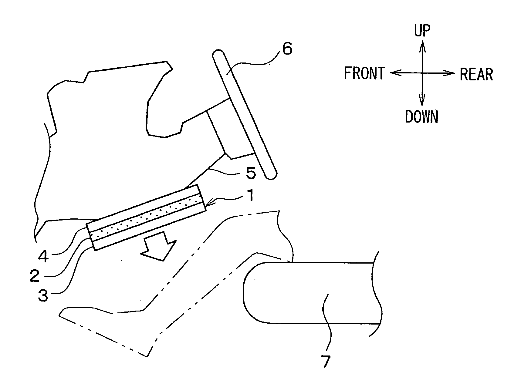
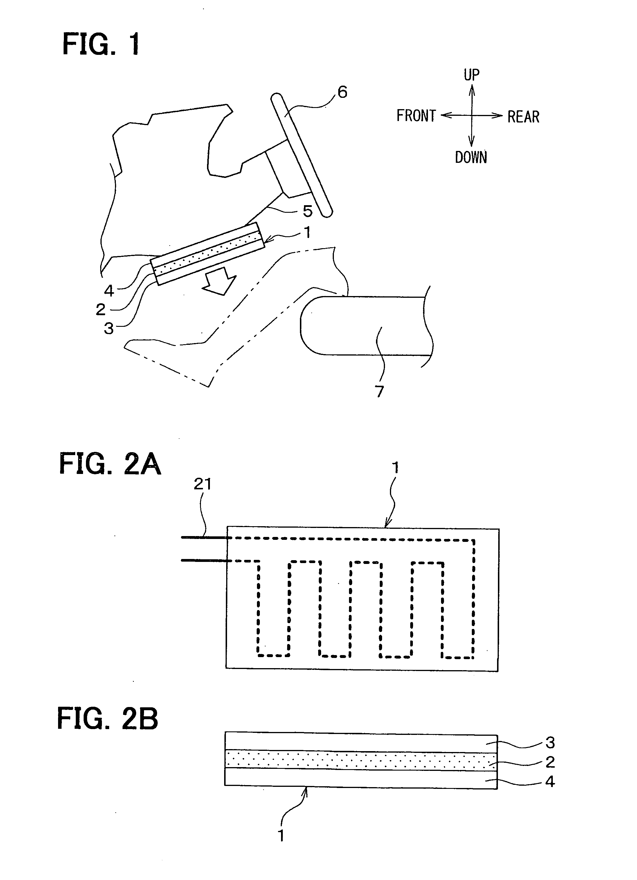
[0035]A first embodiment of the invention will be described in reference to FIGS. 1 to 2B. Directions of arrows illustrating “up, down, front, and rear” in FIG. 1 indicate a positional relation in a state in which a radiation heating system 1 for a vehicle in accordance with the first embodiment is disposed in the vehicle.
[0036]The vehicle, in which this radiation heating system 1 is disposed, also includes a heating system that warms up a vehicle interior with engine coolant as its heat source. The radiation heating system 1 of the present embodiment is used as an auxiliary heating system that is activated when the heat source for warming up the vehicle interior cannot be sufficiently obtained from the engine coolant, such as at the time of starting an engine of the vehicle, and that immediately warms up the vicinity of a foot of an occupant of the vehicle indicated by an alternate long and two short dashes line in FIG. 1.
[0037]The radiation heating system 1 for the vehicle include...
second embodiment
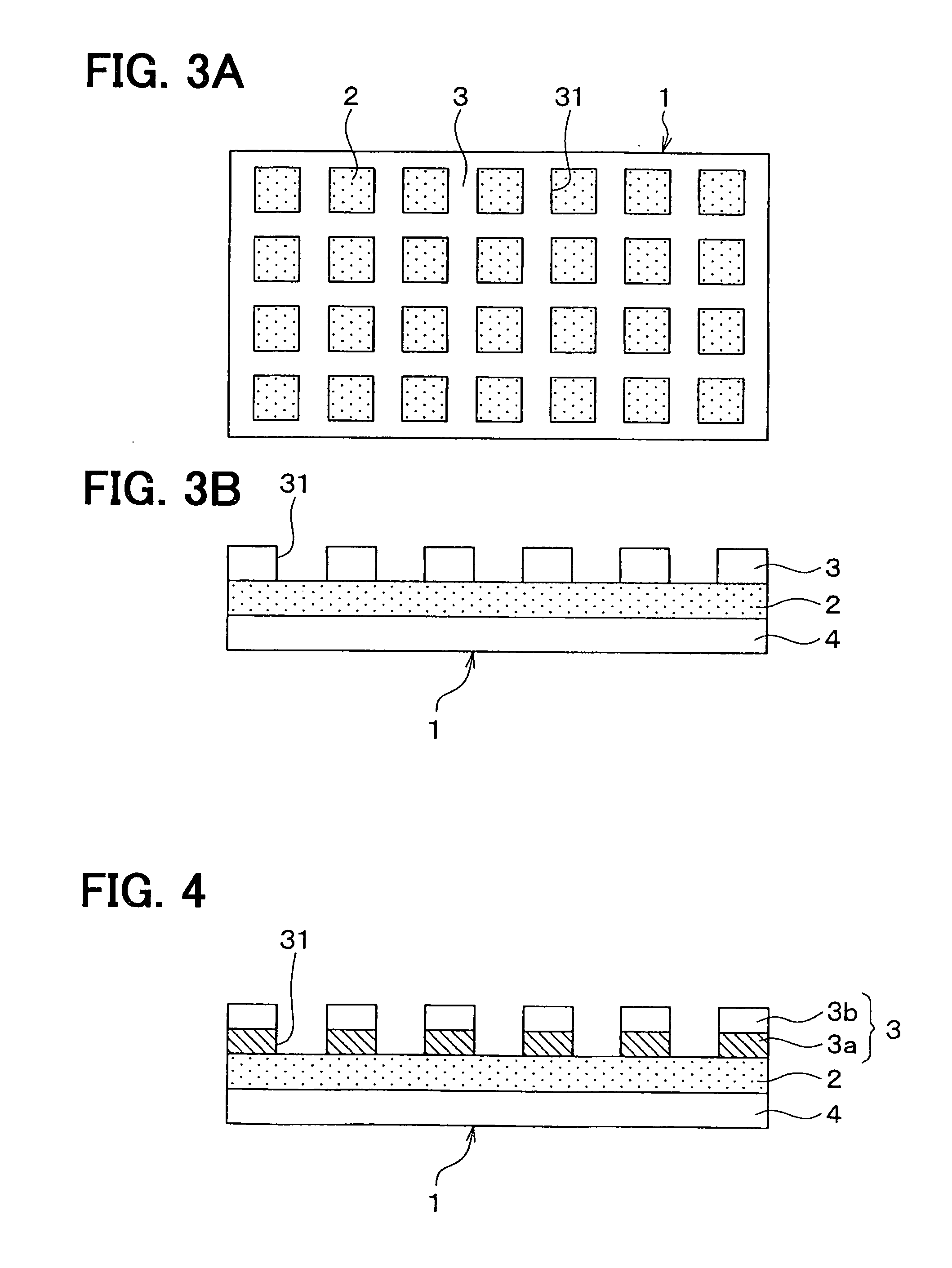
[0043]A second embodiment of the invention will be described with reference to FIGS. 3A and 3B. The second embodiment is different from the above first embodiment in formation of a through hole 31 for an exterior member 3.
[0044]As illustrated in FIGS. 3A and 3B, the through holes 31 passing through both sides of the member 3 are provided for the exterior member 3. Energy of radiation from an electric heater 2 is released directly into the vehicle interior through this through hole 31.
[0045]By forming the through hole 31 in the exterior member 3 as in the present embodiment, radiation heat of the electric heater 2 can be transmitted directly to the occupant via the through hole 31. As a result, the temperature of the portion of the heating system 1 that is in direct contact with the occupant can be decreased, and the occupant's sense of warmth can be improved.
third embodiment
[0046]A third embodiment of the invention will be described with reference to FIG. 4. The third embodiment is different from the above second embodiment in that an exterior member 3 is formed in a double-layered structure.
[0047]As illustrated in FIG. 4, the exterior member 3 has the double-layered structure, which is made up of a first exterior member 3a that is in direct contact with an electric heater 2, and a second exterior member 3b that is in direct contact with the first exterior member 3a. The second exterior member 3b is disposed on the vehicle interior-side of the first exterior member 3a, and the member 3b is arranged not to be in direct contact with the electric heater 2.
[0048]The first exterior member 3a has a higher heat resistance than the second exterior member 3b. Specifically, the first exterior member 3a is made of fluorine-contained rubber or silicone rubber, and the second exterior member 3b is formed from foamed resin.
[0049]As described above, by forming the ex...
PUM
 Abstract
Description
Claims
Application Information