Collision Effect And Particle Information Update In Particulate Fluid Flow Simulations

a particle information and fluid flow technology, applied in the field of collision effect and particle information update in particulate fluid flow, can solve the problem of small cost (in terms of cpu time) of taking surface integrals compared to cos

Inactive Publication Date: 2012-03-15
SEIKO EPSON CORP
View PDF2 Cites 18 Cited by
  • Summary
  • Abstract
  • Description
  • Claims
  • Application Information

AI Technical Summary

Benefits of technology

This patent describes an invention that allows researchers to simulate how particles behave when they collide in a computer model. The system uses instructions on how to calculate the forces between the particles, and also tracks their movement over time. By doing this, scientists can better understanding what happens when materials move through space.

Problems solved by technology

The patent text discusses the importance of particulate fluid flows and the difficulty in simulating them using traditional methods. The technical problem addressed in the patent is the need for an algorithm that can solve the nonlinear Navier-Stokes equations and the particle effect simultaneously to accurately simulate particulate fluid flows with rigid solid particles.

Method used


Image

  • Collision Effect And Particle Information Update In Particulate Fluid Flow Simulations
  • Collision Effect And Particle Information Update In Particulate Fluid Flow Simulations
  • Collision Effect And Particle Information Update In Particulate Fluid Flow Simulations

Examples


Embodiment Construction

I. Updating Particle Information

[0028]1. Governing Equations

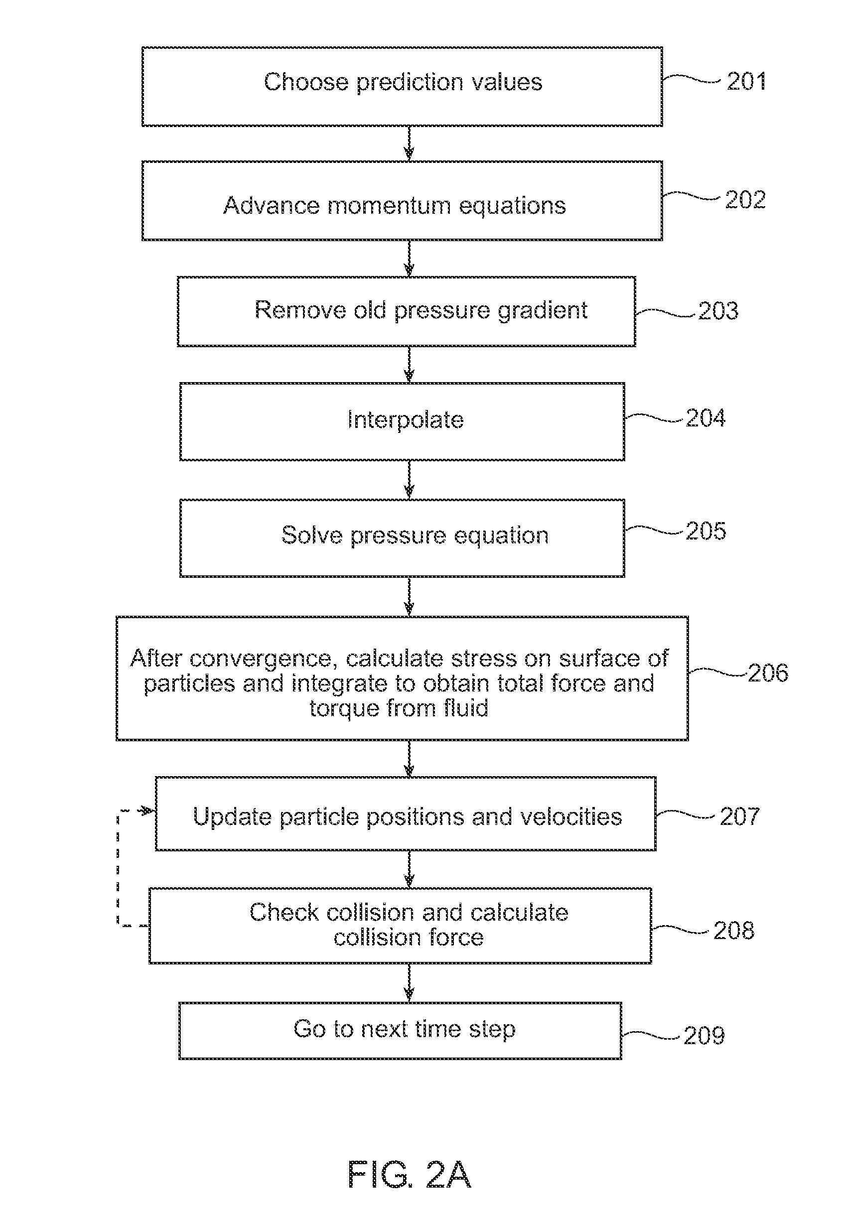
[0029]One set of equations to be used is the momentum equations, which equations are to be solved in the entire domain (fluid and solid particles). The momentum equations are given by equations (1) and (2), which, along with the other equations numerically-referenced below, are set forth in the Appendix of the specification. In equation (2), ΘP is an indicator function, which equals: 1 for each mesh cell completely occupied by particles, 0 for fluid, and is the ratio of the volume occupied by particles to the volume of the mesh cell.

[0030]Another equation to be used is the continuity equation, which is given as equation (3).

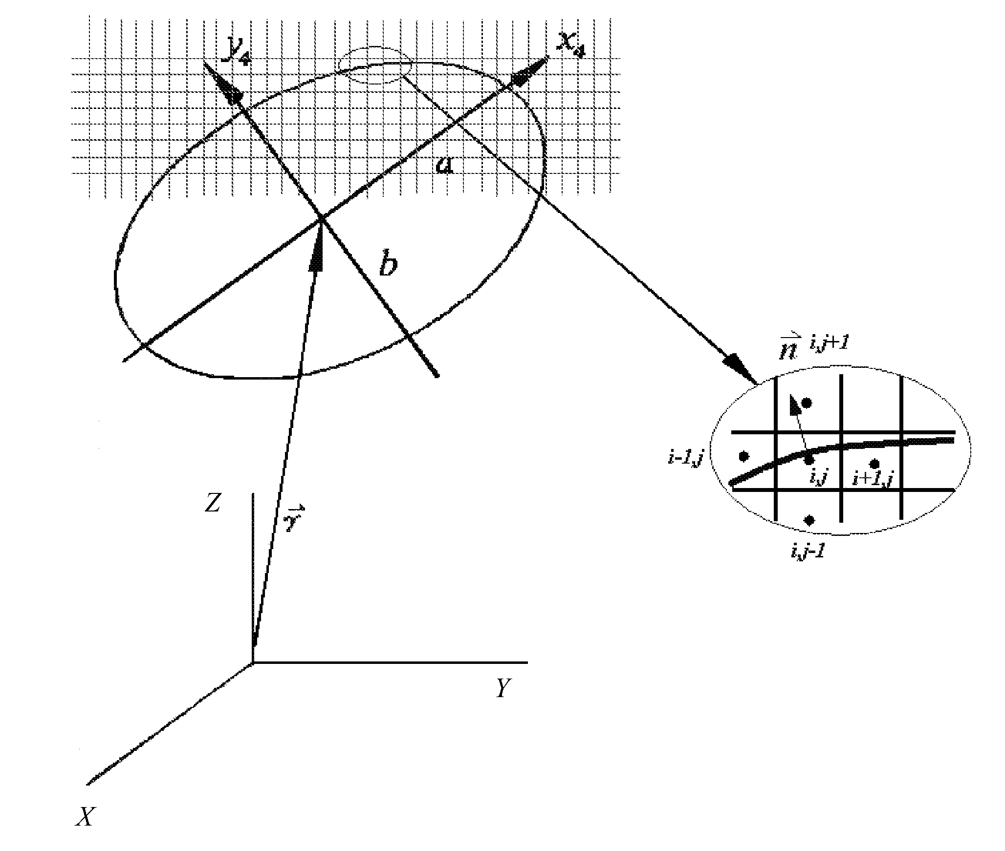
[0031]Because the particles are rigid bodies, a rigidity constraint is required, which leads to the vanishing of the deformation rate tensor, as shown in equation (4), where {right arrow over (U)} is the velocity of the particles' center of mass, {right arrow over (ω)} is the angular velocity of the part...


PUM


Abstract

To update particle information in a particulate fluid flow simulation, the new positions of the particles are determined by the balance of all forces, and such forces are calculated by taking surface integrals along the particle-fluid interface to reduce CPU overhead. A 3-D collision scheme for ellipsoidal particles to determine whether two or more ellipsoidal particles in the fluid flow collide, and if so, determine the location of the collision point between two colliding particles is also disclosed. Other aspects involve predicting the new location and orientation of each of the colliding particles after collision.

Description


Claims


Application Information

Patent Timeline
Owner SEIKO EPSON CORP
Why Eureka
Try Eureka