Electrical receptacle

Inactive Publication Date: 2012-03-22
TSAI CHOU HSIEN
View PDF0 Cites 22 Cited by
  • Summary
  • Abstract
  • Description
  • Claims
  • Application Information

AI Technical Summary

Benefits of technology

[0008]The present invention further provides an electrical receptacle for minimizing the adverse influence of the crosstalk or electromagnetic interference on the interface signals during operations of various high-speed

Problems solved by technology

Since the transmission speed of the universal serial bus 2.0 (also referred as USB 2.0) interfac

Method used


Image

  • Electrical receptacle
  • Electrical receptacle
  • Electrical receptacle

Examples


Example

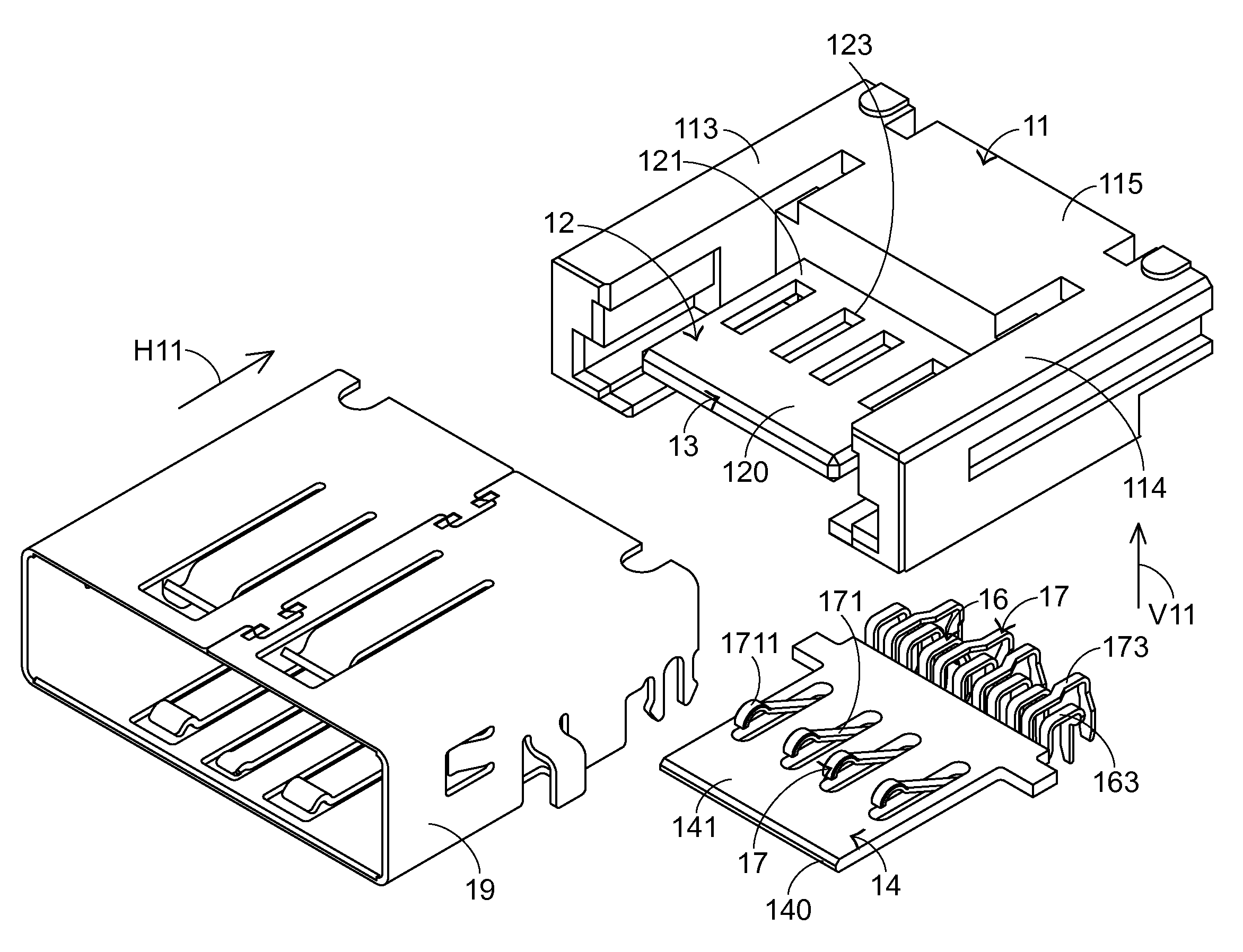
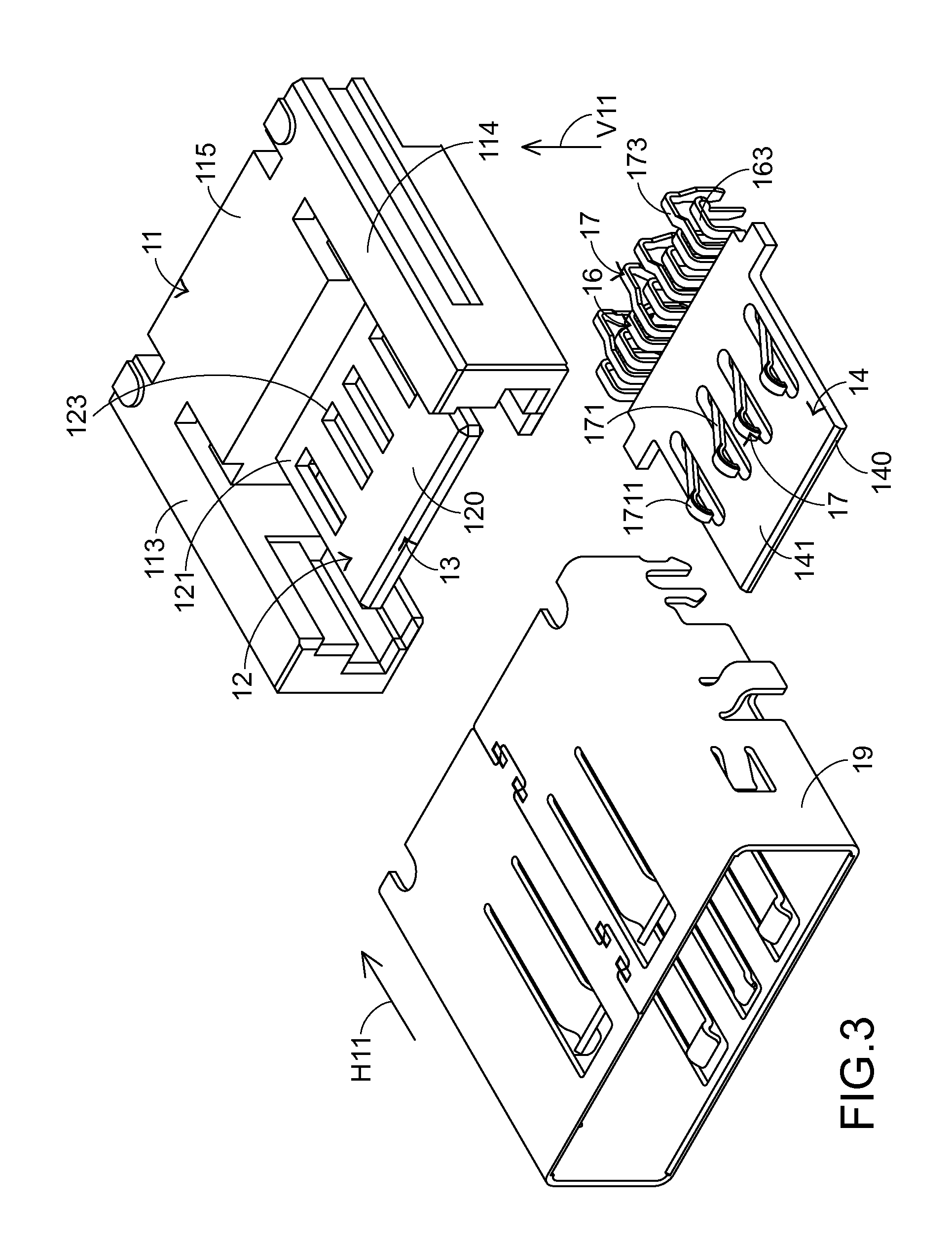
[0126]In another embodiment (not shown, but will be described in the second embodiment), from front to back, the USB 2.0 signal interface successively comprises a plurality of contact resilience arm segments, a plurality of extension segments, and a plurality of pin segments. The extension segments are electrically connected with respective contact resilience arm segments and disposed within the second docking space 122. The pin segments are electrically connected with respective extension segments. That is, the USB 2.0 signal interface 17 also comprises a plurality of USB 2.0 conductive terminals, but the extension segments 172 are disposed within the second docking space 122.

[0127]In a further embodiment (not shown), from front to back, the USB 2.0 signal interface successively comprises a plurality of contact resilience arm segments, a plurality of extension segments, and a plurality of pin segments. The extension segments are electrically connected with respective contact resili...

Example

[0144]In comparison with the first embodiment, the electrical receptacle 30 of this embodiment further comprises a third signal interface 50. The third signal interface 50 is arranged between the tongue plate 32 and the circuit board 34. In this embodiment, the third signal interface 50 comprises a plurality of conductive terminals. Moreover, the third signal interface 50 and the USB 2.0 signal interface are collaboratively defined as a USB3.0 signal interface.

[0145]In this embodiment, a plurality of contact holes 324 are located at the front end of the tongue plate 32. These contact holes 324 run through the first surface 321 and the second surface 322 of the tongue plate 32 for accommodating respective contact segments 501 of the conductive terminals of the third signal interface 50. Moreover, a plurality of terminal recesses 3221 are formed in the second surface 322 of the tongue plate 32 and extended from the contact holes 324 toward the bottom part 315 of the main body 31. The ...

Example

[0153]In comparison with the third embodiment, the tongue plate 82 of the electrical receptacle 80 of this embodiment is located under the circuit board 84. The other components and mechanisms of the electrical receptacle 80 with respect to the tongue plate 72 and the circuit board 74 are similar to those of the fourth embodiment, and are not redundantly described herein.

[0154]FIG. 14 is a schematic side view illustrating an electrical receptacle according to a sixth embodiment of the present invention. Except for the following items, the other components and mechanisms of the electrical receptacle of this embodiment are similar to those of the fourth embodiment, and are not redundantly described herein.

[0155]As shown in FIG. 14, the circuit board 74 has a plurality of conductive holes 744 running through the first surface 741 and the second surface 742 of the circuit board 74. The extension wires of the first signal interface 76 that are disposed on the second surface 742 of the ci...


PUM


Abstract

An electrical receptacle includes a plastic main body, a plastic tongue plate, and a circuit board. The plastic main body has a first docking space and a second docking space. The plastic tongue plate has a first surface, a second surface, and a plurality of slots. The slots run through the first surface and the second surface of the plastic tongue plate. The circuit board has a first surface, a second surface, and a plurality of grooves. The grooves run through the first surface and the second surface of the circuit board. The circuit board is accommodated within the second surface of the plastic tongue plate. Moreover, the first surface of the circuit board is arranged beside the second surface of the plastic tongue plate.

Description

FIELD OF THE INVENTION[0001]The present invention relates to an electrical receptacle, and more particularly to an electrical receptacle with a single type of signal interface or various types of signal interfaces and with a novel receptacle structure.BACKGROUND OF THE INVENTION[0002]Nowadays, the functions of various electronic products become more powerful. Since handheld devices are increasingly popular, the demands on the data transmission between various electronic products or handheld devices are increased. As the volume of the electronic product or the handheld device is gradually reduced, there is a need of installing more connecting interfaces (e.g. electrical receptacles) on the casing's peripheral profile (also referred as a casing's coastline) of the electronic product or the handheld device so as to exchange signals between different devices.[0003]For example, in accordance with a widely-used method, various signal interfaces may be integrated into a single electrical r...

Claims


Application Information

Patent Timeline
IPC IPC(8): H01R24/28
CPCH01R12/724H01R13/6658H01R13/6471
Inventor TSAI, CHOU-HSIEN
Owner TSAI CHOU HSIEN
Why Eureka
Try Eureka