Air cooling & humidifying device and method within buildings

Inactive Publication Date: 2012-03-29
NAT CHIN YI UNIV TECH +1
View PDF0 Cites 1 Cited by
  • Summary
  • Abstract
  • Description
  • Claims
  • Application Information

AI Technical Summary

Benefits of technology

[0007]The primary objective of the present invention is to provide an air cooling & humidifying device and method within buildings, which could improve air-conditioning efficiency and also accelerate heat exchange for rapid air humidifying and temperature drop as a way of energy-saving and emission reduction.

Problems solved by technology

Continuous human activities have caused global climate warming and consequently various kinds of natural disasters.

Method used


Image

  • Air cooling & humidifying device and method within buildings
  • Air cooling & humidifying device and method within buildings
  • Air cooling & humidifying device and method within buildings

Examples


Embodiment Construction

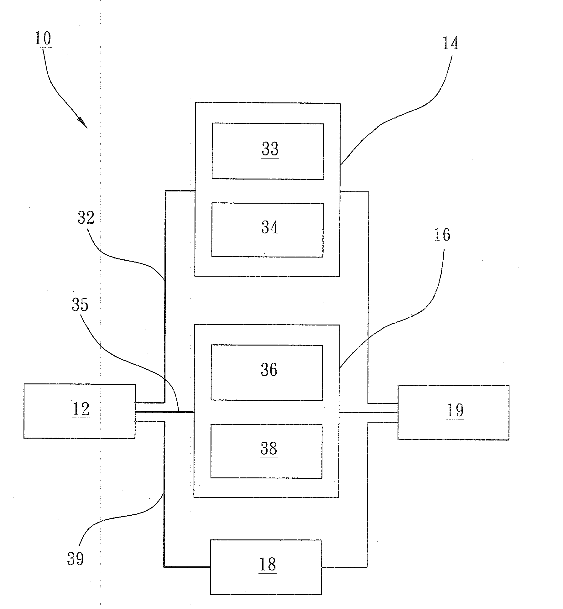
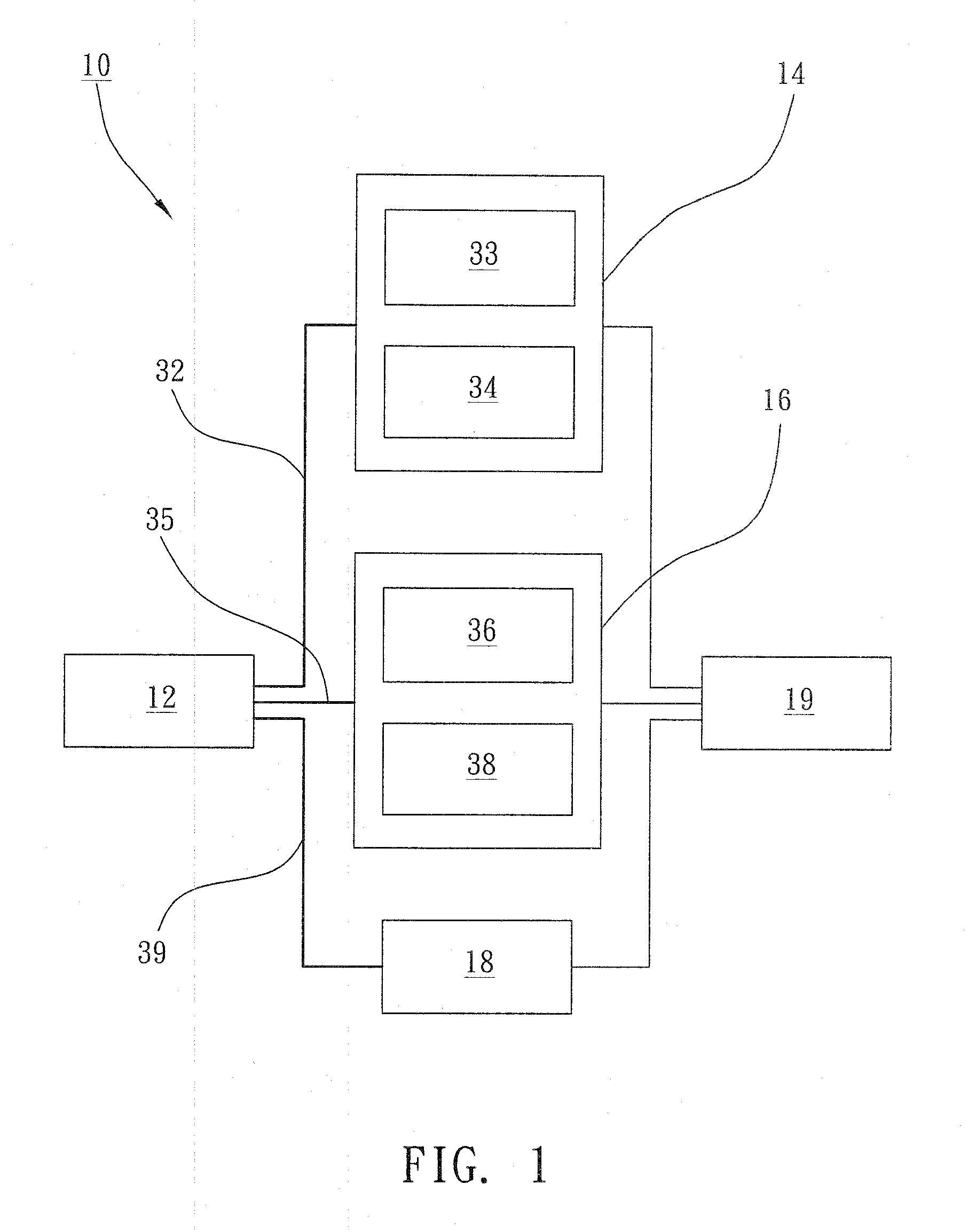
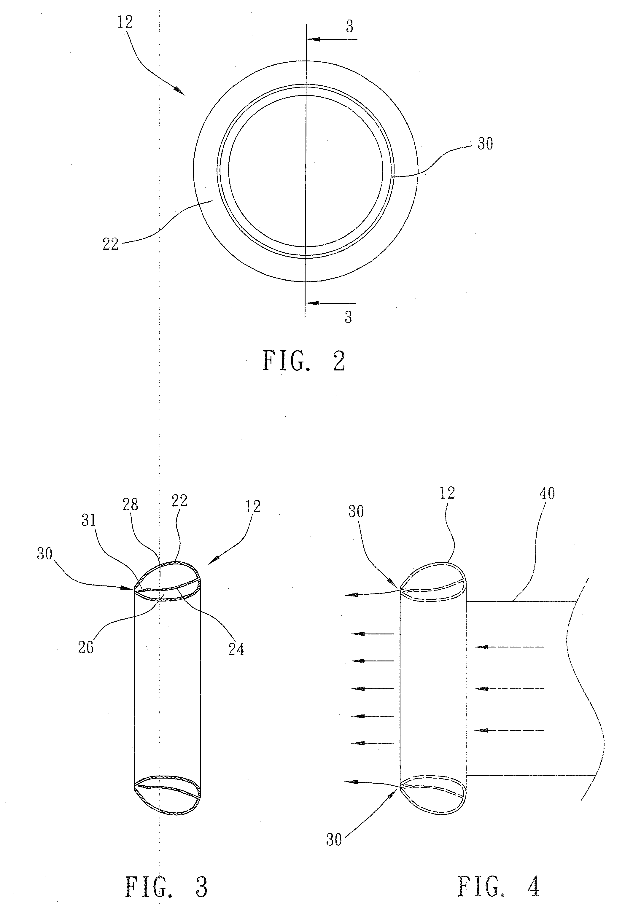
[0016]Referring to FIGS. 1-3, air cooling & humidifying device 10 of the present invention is applied to air conditioning industry, which comprising: an air supply unit 12, a high-pressure air generator 14, a low-pressure air generator 16 and an atomizer 18.

[0017]The air supply unit 12 is provided with a looped hollow frame 22, wherein a partition 24 is extended to segregate it into a high-pressure air chamber 26 and a low-pressure air chamber 28; an air vent 30 of looped slot extended to one side of the frame 22 and connected with high-pressure air chamber 26 and low-pressure air chamber 28; a platy regulator 31, made of elastic material, arranged at one side of the air vent 30, and used to withstand air pressure and regulate the aperture of the air vent 30.

[0018]The high-pressure air generator 14 is connected with the high-pressure air chamber 26 via a transfer pipe 32, and consists of a motor 33 and a fan 34, of which the motor 33 is used to drive the fan 34 for generating and fe...


PUM


Abstract

An air cooling and humidifying device comprises an air supply unit, a high-pressure air generator, a low-pressure air generator and an atomizer. The air supply unit comprises several air vent, a high-pressure air chamber, and a low-pressure air chamber connected with the air vents. The high-pressure air generator is connected with the high-pressure air chamber to generate high-pressure air to be sent to the high-pressure air chamber. A low-pressure air generator is connected with the low-pressure air chamber to generate low-pressure air to be sent to the low-pressure air chamber. An atomizer is connected with the high-pressure air chamber to atomize water for mixing into high-pressure air.

Description

BACKGROUND OF INVENTION[0001]1. Field of the Invention[0002]The present invention relates generally to an air conditioning technology within buildings, and more particularly to an innovative air cooling & humidifying device and method within buildings.[0003]2. Description of Related Art[0004]Air conditioners and relevant technologies are continuously researched for a more comfortable living environment. In recent years, some dissertations and patents have devoted a great deal of space to air conditioning technologies, which are thus developed into mature technologies for the benefit of the human beings.[0005]Continuous human activities have caused global climate warming and consequently various kinds of natural disasters. For the purpose of sustainable growth and development of the human beings, it is critical to encourage energy conservation and reduce CO2 emissions, especially for air conditioners which will consume huge energy and drain CO2 generated in energy conversion into atm...

Claims


Application Information

Patent Timeline
IPC IPC(8): F28D5/00F25D17/06
CPCF24F6/12F28D21/0015F24F2006/143
Inventor WENG, KUO-LIANG
Owner NAT CHIN YI UNIV TECH
Why Eureka
Try Eureka