Heat removal device of communication electrical appliance

A technology for heat removal devices and electrical appliances, which is applied in cooling/ventilation/heating transformation, chassis/cabinet/drawer parts, etc., to avoid interference, avoid influence, and improve the efficiency of air conditioning

Active Publication Date: 2015-01-28
宁波英科特精工机械股份有限公司
View PDF3 Cites 0 Cited by
  • Summary
  • Abstract
  • Description
  • Claims
  • Application Information

AI Technical Summary

Problems solved by technology

[0005] How to ensure effective heat dissipation and maximize the number of cabinets under the premise of limited space and air conditioning investment has become a bottleneck restricting the further improvement of functions in the data center

Method used


Image

  • Heat removal device of communication electrical appliance
  • Heat removal device of communication electrical appliance
  • Heat removal device of communication electrical appliance

Examples


Embodiment Construction

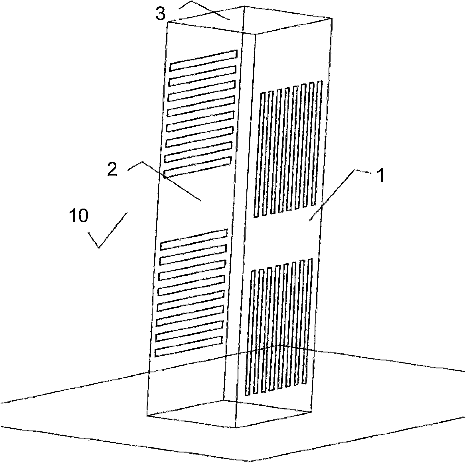
[0014] This creation discloses a heat exhaust device for communication appliances, and the communication appliances are arranged in an electrical cabinet. figure 1 The three-dimensional schematic diagram of the cabinet 10 in the present invention is shown. The common cabinet is a rectangular parallelepiped with a certain height, which includes: the inlet end face 1 for entering the cooling gas and the exhaust end face 2 for discharging the heating gas, and the top 3 of the cabinet. Usually the cabinet basically provides protection and support for a pair of internal equipment in a closed structure.

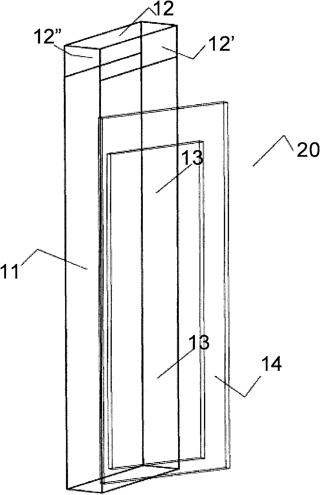
[0015] figure 2 It is a three-dimensional schematic diagram of the cabinet in which the device is installed in the present invention. This figure is an example of the device 20 installed on the inlet end face 1 where the cooling gas enters. It should be pointed out that the exhaust end face 2 installed on the cabinet 10 to discharge the heating gas also has a similar structure an...


PUM


Abstract

The invention discloses a heat removal device of a communication electrical appliance. The communication electrical appliance is arranged in a cabinet; the cabinet is provided with an air-inlet end face from which cooling air is fed and an air-exhaust end face from which heating air is exhausted; at least one of the end faces is provided with an air guide device, and the air guide device is provided with a guide bin with a substantial thickness in the direction perpendicular to the end face of the cabinet so as to ensure enough air is guided; the guide bin is provided with a first air guide port matched with the end face of the cabinet and a second air guide port connected with the air outside the cabinet; the air guide device is substantially sealed so as to be suitable for the air cooling of the cabinet, so that after passing through the second air guide port, the guide bin and the first air guide port, the air outside the cabinet is connected with an air path on the end face of the cabinet; and a part, opposite to the end face of the cabinet, of the air guide device is provided with a bin gate, and the bin gate is preferably made of transparent materials so as to facilitate operation and observation.

Description

technical field [0001] The invention relates to a communication cabinet, especially its heat exhausting device. Background technique [0002] With the development of communication and electronic integrated monitoring technology, servers and data centers are widely used, and the cabinet has undoubtedly become the basic unit and carrier of these data centers and servers. There are usually multiple cabinets in an independent closed room in the data center, and a large number of electrical equipment and components are installed in each cabinet, such as common printed circuit boards, which are arranged in a compact and orderly manner and input current to realize the corresponding function. The data shows that the input current per cabinet is about 10A, and a considerable part of this current will be converted into heat and dissipated. The released heat will react to the surrounding electrical components and affect its normal operation. Therefore, it is necessary to discharge th...

Claims


Application Information

Patent Timeline
Patent Type & Authority Patents(China)
IPC IPC(8): H05K7/20H05K5/02
Inventor 应兴隆
Owner 宁波英科特精工机械股份有限公司
Why Eureka
Try Eureka