Supercharge Your Innovation With Domain-Expert AI Agents!

Terminal Assembly

a technology of terminals and assemblies, applied in the direction of coupling device connections, securing/insulating coupling contact members, contacts, etc., can solve the problems of difficult assembly of terminals with the case, difficult to hold the terminals, and complicated structure of the case, so as to prevent the terminal from loosening and moving, and the assembly is difficult. , the effect of lack of spa

Inactive Publication Date: 2012-03-29
YU TSUNG MOU
View PDF13 Cites 2 Cited by
  • Summary
  • Abstract
  • Description
  • Claims
  • Application Information

AI Technical Summary

Benefits of technology

This patent describes an improved design for a terminal assembly that solves problems associated with older designs such as difficulty in assembly, limited space within the device, and complex manufacturing processes. The new design uses a curved part on both the terminal and the case, allowing them to connect more securely without requiring extra parts or stopping plates. This simplifies the construction process and increases internal space while reducing costs.

Problems solved by technology

The technical problem addressed by this patent is how to design a switch device that can easily assembly and securely keep its components in place without adding complexity or increasing costs.

Method used


Image

  • Terminal Assembly
  • Terminal Assembly
  • Terminal Assembly

Examples


Embodiment Construction

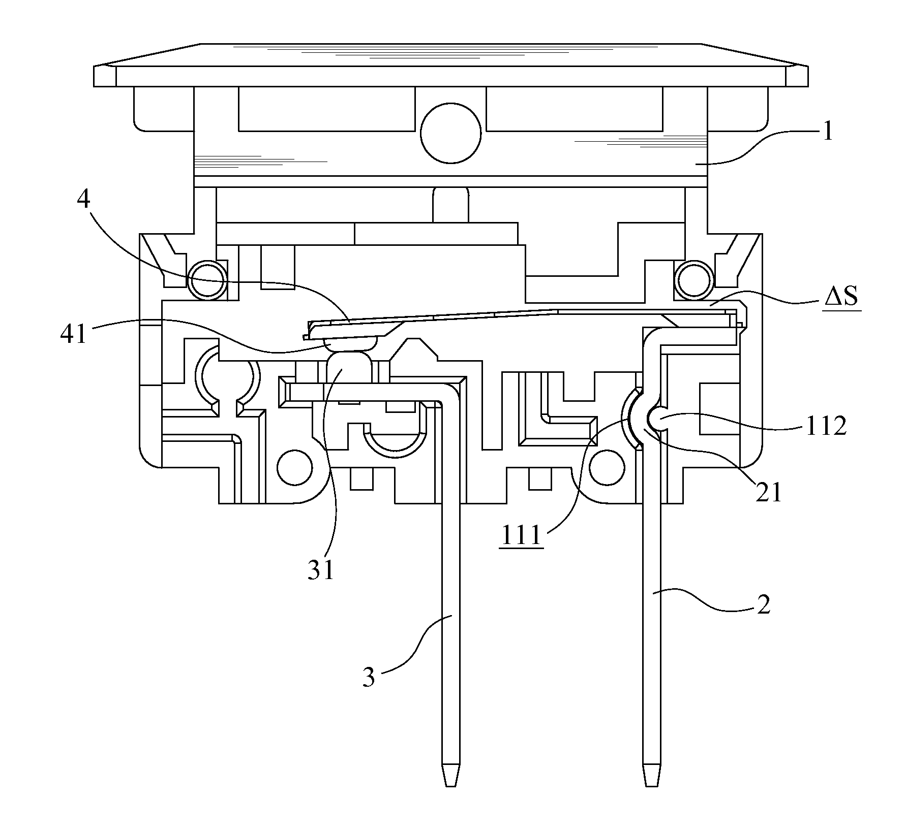
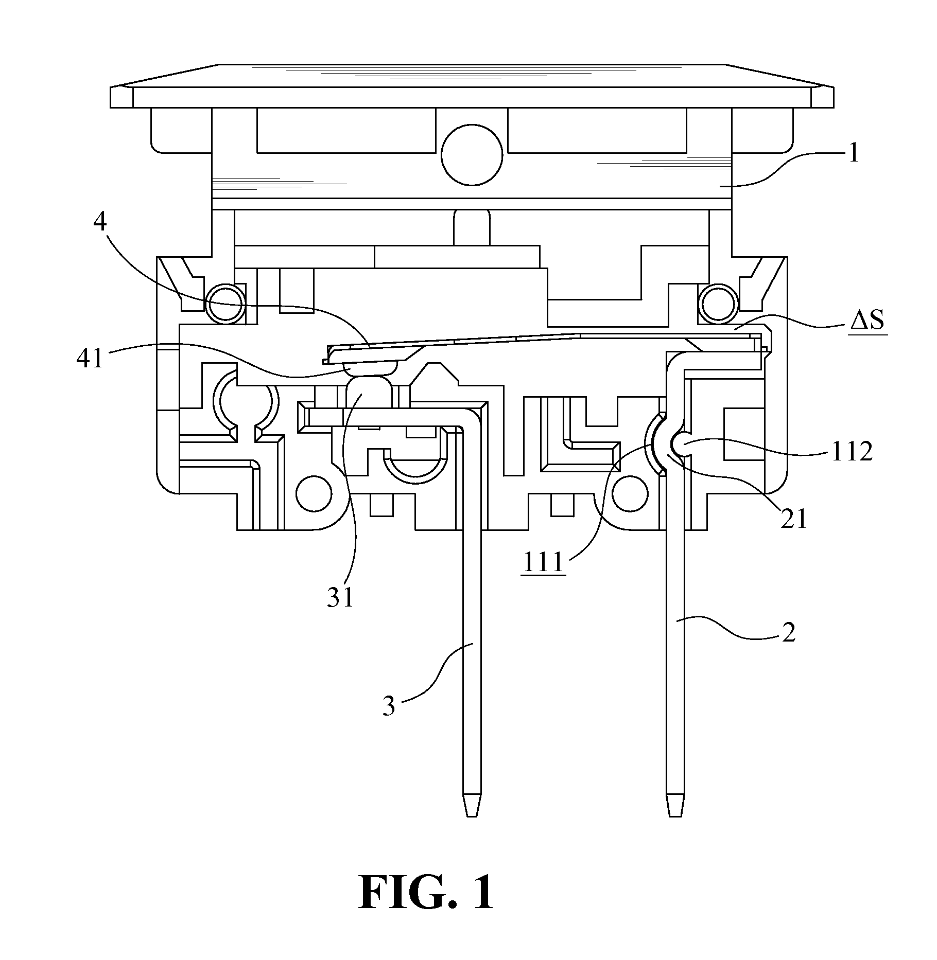
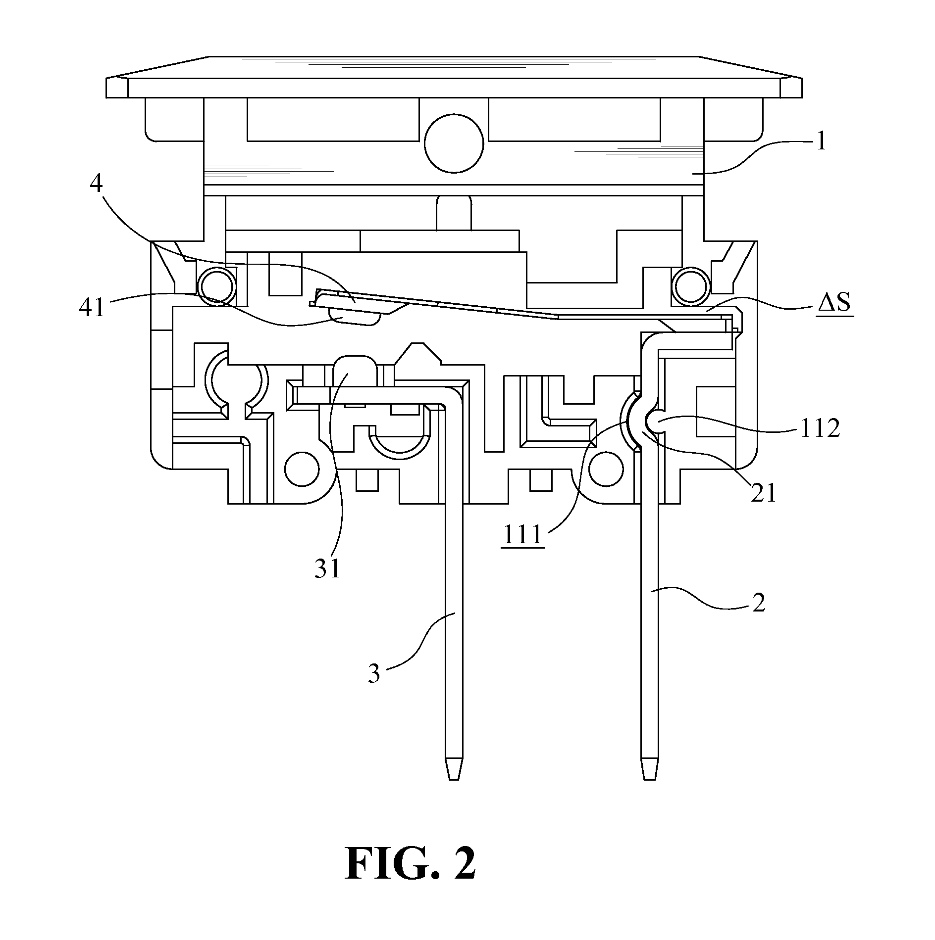
[0014]With reference to FIGS. 1 to 4, a terminal assembly according to the present invention is used in a switch device and comprises a hollow case 1, a first terminal 2, a second terminal 3 and a contact piece 4.

[0015]The case 1 includes a first slot 11 and a second slot 12 defined through a bottom thereof.

[0016]The first terminal 2 and the second terminals 3 are in L-shaped and engaged with the first slot 11 the second slot 12, respectively. Bottom ends of the first terminal 2 and the second terminal 3 extend out of the case 1. A second contact point 31 is connected to the top end of the second terminal 3.

[0017]The contact piece 4 is a strip which is used to connected or disconnect the first terminal 2 and the second terminal 3. The contact piece 4 may be an alloy strip and has a bent portion 40 as shown in FIG. 4. The bent portion 40 allows the contact piece 4 to bend toward one side thereof and the contact piece 4 bends toward the other side thereof when being overheated. The co...


PUM


Abstract

A terminal assembly for a switch device includes a hollow case, two terminals, two slots respectively corresponding to the terminals and a contact piece. The terminal includes a curved portion and the slot includes a curved slot corresponding to the curved portion. The case has a protrusion disposed corresponding to the curved slot. When assembling the terminal with the case, the terminal is received in the slot, the curved portion is engaged with the curved slot and the protrusion is pressed against a concave side of the curved portion. Therefore, the terminal is securely connected with the case and the terminal does not move or get loosened during use.

Description


Claims


Application Information

Patent Timeline
Owner YU TSUNG MOU
Features
  • R&D
  • Intellectual Property
  • Life Sciences
  • Materials
  • Tech Scout
  • Unparalleled Data Quality
  • Higher Quality Content
  • 60% Fewer Hallucinations
Learn More