Driving belt and method for assembling the same

a technology of driving belts and components, applied in the field of driving belts, can solve the problems of reducing the efficiency or productivity of the driving belt, increasing the transmission loss, and thereby degrading the power transmission efficiency, so as to reduce the endplay, reduce the endplay, and form easily

Inactive Publication Date: 2014-04-17
TOYOTA JIDOSHA KK
View PDF30 Cites 13 Cited by
  • Summary
  • Abstract
  • Description
  • Claims
  • Application Information

AI Technical Summary

Benefits of technology

[0018]Alternatively, a flat face may also be formed on the inserting member. In this case, the flat face formed on the inserting member is contacted with the rocking edge of the adjoining element under the situation in which the inserting member is inserted into the insertion groove of the adjuster element to reduce the endplay. That is, the flat face serves as a receiving face of a reaction force from the rocking edge. Therefore, the adjuster element serves as the other elements. Further, the flat face may be formed easily on the inserting member in comparison with forming a curved face or an edge thereon. For this reason, according to the present invention, the driving belt can be manufactured easily.
[0019]As also described, according to the driving belt of the present invention, the second insertion groove may be formed on the head portion of the adjuster element situated in the outer circumferential side, in addition to the first insertion groove formed at the level in the vicinity of the level at which the rocking edge of the other element is situated. In this case, the first inserting member is inserted into the first insertion groove, and the second inserting member is inserted into the insertion groove. That is, the adjuster element is contacted with the adjoining element at two different levels. Therefore, the attitude of the adjuster element in the element array can be stabilized. In other words, the adjuster element can be contacted with the adjoining element in a same condition as the other elements. Thus, the adjuster element serves as the other elements also in this case.
[0020]In addition, according to the present invention, the adjuster element further comprises the disengagement preventing means configured to engage the inserting member inserted into the insertion groove with the insertion groove in case the inserting member is inserted into the insertion groove to reduce the endplay. Therefore, the inserting member can be prevented from being disengaged from the adjuster element even after fastening the elements by the ring.
[0021]Meanwhile, according to the assembling method of the present invention, the driving belt is assembled using the adjuster element thus structured together with the other standard elements. Therefore, the driving belt can be assembled easily, that is the productivity of the driving belt can be improved, while improving a power transmitting efficiency.

Problems solved by technology

However, in case the end play is too small, the last piece of the element is difficult to be inserted into the element array and easiness or productivity of the driving belt is thereby degraded.
In this case, however, a transmission loss is increased due to a slippage between the elements and the ring, and a power transmitting efficiency is thereby degraded.
Therefore, if the length of the projection is too short, the element array cannot be aligned.
In addition, durability and transmission efficiency of the driving belt may be degraded.
Therefore, an assembly cost and number of assembling steps of the metal belt have to be increased in comparison with those of the other conventional driving belts.
Thus, the transmission loss resulting from the slippage may not be reduced sufficiently even if the “spring means” are used in the driving belt.

Method used


Image

  • Driving belt and method for assembling the same
  • Driving belt and method for assembling the same
  • Driving belt and method for assembling the same

Examples


Embodiment Construction

[0045](Structure of the Driving Belt)

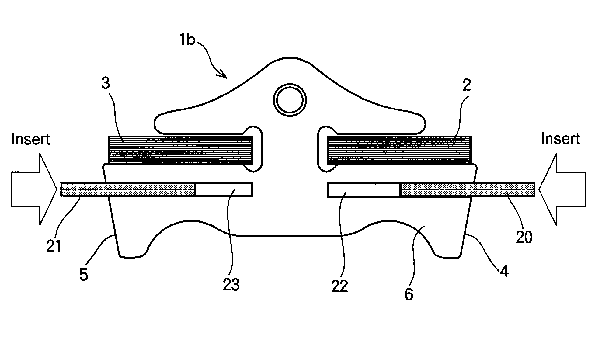
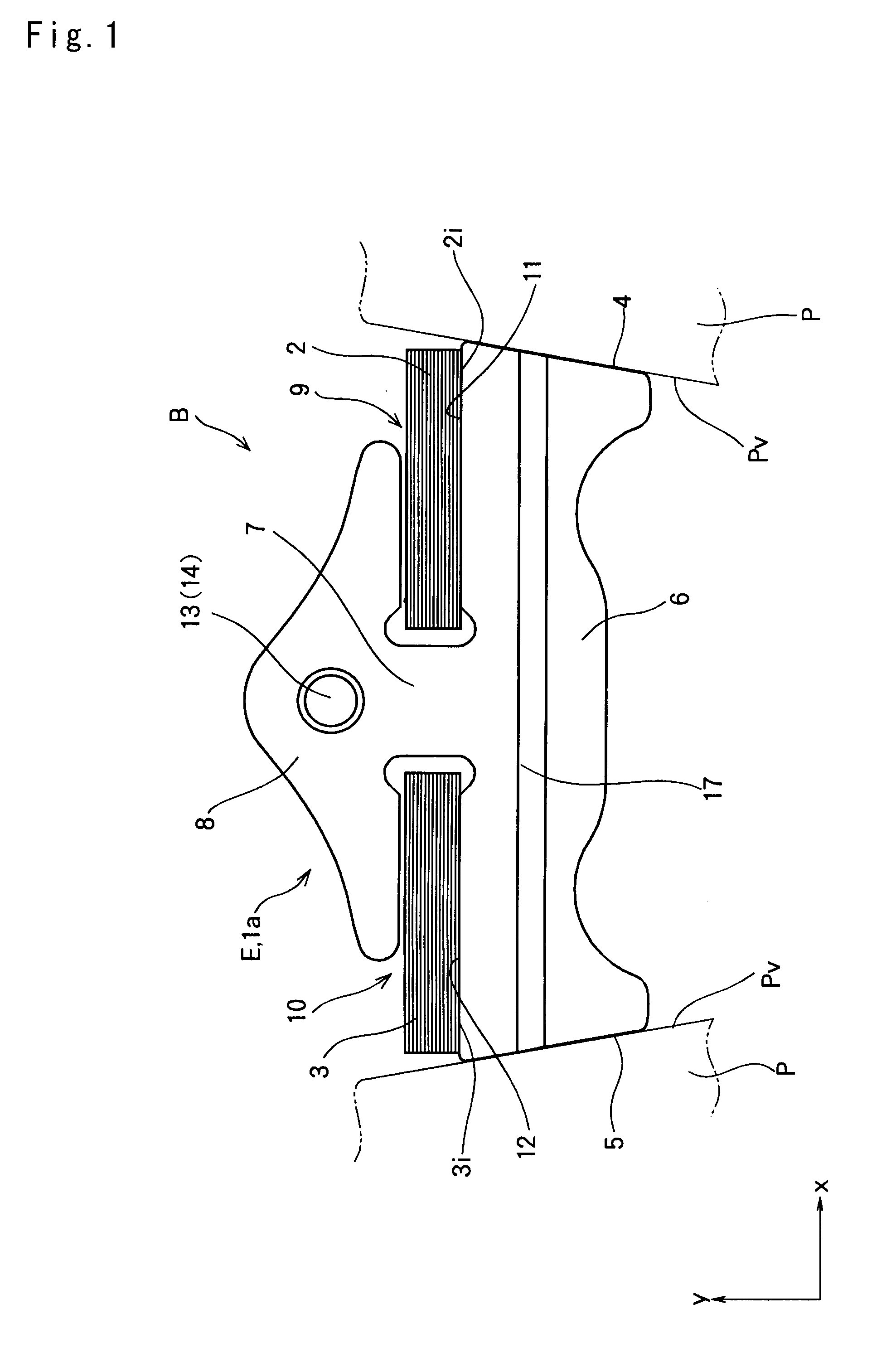
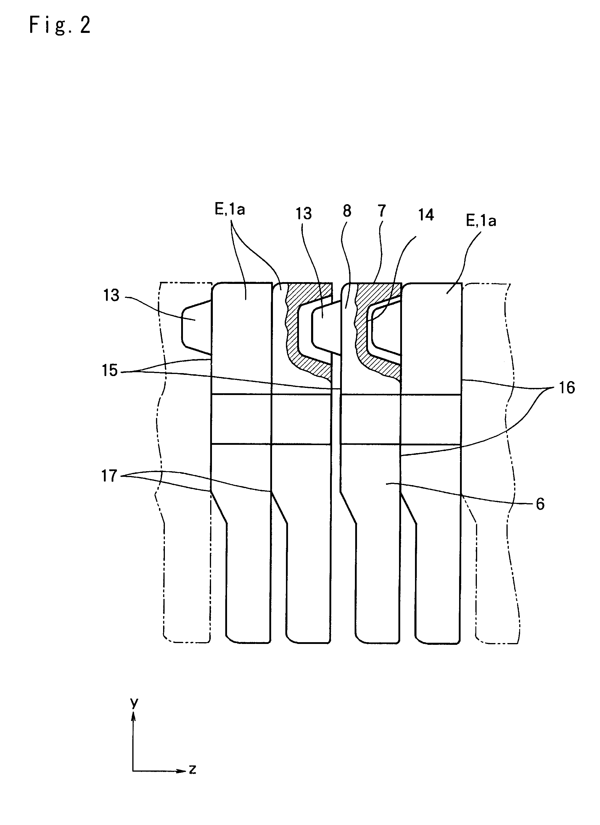
[0046]Next, examples of a structure of the driving belt according to the present invention will be explained hereinafter with reference to the accompanying drawings. For example, a driving belt to which the present invention is applied is used in a belt-type continuously variable transmission for a vehicle. Specifically, the driving belt is applied to a V-groove of a pulley formed between a pair of sheaves to transmit a torque by a friction force established between the belt and the pulley. A fundamental structure of the driving belt is schematically shown in FIGS. 1 to 4. As shown in FIGS. 1 and 3, a driving belt B is applied to a pair of (driving and driven) pulleys P forming a transmission mechanism of the belt-type continuously variable transmission. Each pulley P is formed by a pair of fixed sheave and movable sheave being opposed to each other, and opposed faces of those sheaves are individually tapered to form a belt groove Pv between thos...


PUM

PropertyMeasurementUnit
thicknessaaaaaaaaaa
transmissionaaaaaaaaaa
transmission lossaaaaaaaaaa

Abstract

A driving belt comprising plate elements juxtaposed in its thickness direction and a flat ring fastening the elements annularly. The elements includes at least one adjuster element configured to adjust an endplay as a total of clearances between the adjacent elements in the elements fastened annularly by the ring. The adjuster element comprises an insertion groove opening toward the endplay, and an inserting member inserted into the insertion groove and configured to protrude partially from the insertion groove thereby adjusting the endplay.

Description

TECHNICAL FIELD[0001]This invention relates to a driving belt formed by fastening a plurality of plate-like elements juxtaposed in a same orientation annularly by a flat ring, and to an assembling method thereof.BACKGROUND ART[0002]A push type driving belt to be used in a belt type continuously variable transmission is known in the prior art. The driving belt of this kind is formed by annularly juxtaposing a plurality of plate members called an “element” or a “block” in a same orientation, and by fastening the juxtaposing plate members by an annular member such as a band, a hoop and a ring.[0003]One example of the above-explained driving belt is disclosed in Japanese Patent Laid-Open No. 2006-266363. According to the “transmission belt” taught by Japanese Patent Laid-Open No. 2006-266363, an element comprises a first hole and a first projection formed at a head part, and a second hole and a second projection formed in an inner circumferential side of a rocking edge. A plurality of t...

Claims


Application Information

Patent Timeline
Patent Type & Authority Applications(United States)
IPC IPC(8): F16G5/16
CPCF16G5/16Y10T29/49895
Inventor HARIMA, KAZUNORIHATTORI, YUJIYOSHIDA, MICHIO
Owner TOYOTA JIDOSHA KK
Why Eureka
Try Eureka