Roadside-vehicle cooperative illumination system

Inactive Publication Date: 2012-03-29
DENSO CORP
View PDF4 Cites 33 Cited by
  • Summary
  • Abstract
  • Description
  • Claims
  • Application Information

AI Technical Summary

Benefits of technology

[0013]With this configuration, the in-vehicle apparatus side detector detects information pertaining to operation of the headlight, such as when power consumption of the headlight has to be reduced and when it is not possible to ensure a sufficient illuminance of the headlight. The in-vehicle apparatus side arbiter transmits a request to the roadside apparatus for increasing at least one of an illuminance and an illumination range of the road illumination lamp on the basis of the detected information.

Problems solved by technology

For example, in the case of a motor-driven vehicle with a reduced SOC (state of charge) of a vehicle battery that supplies electrical power to the vehic

Method used


Image

  • Roadside-vehicle cooperative illumination system
  • Roadside-vehicle cooperative illumination system
  • Roadside-vehicle cooperative illumination system

Examples


Embodiment Construction

[0019]The present invention will be described more fully hereinafter with reference to the accompanying drawings. Like numbers refer to like elements throughout.

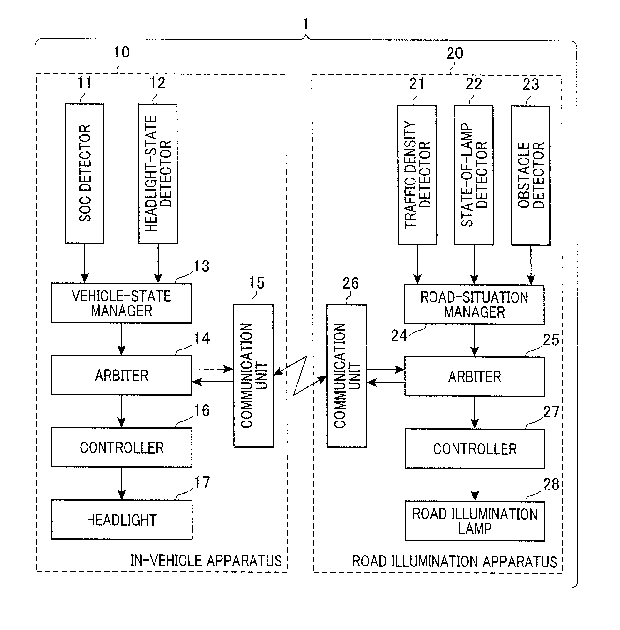
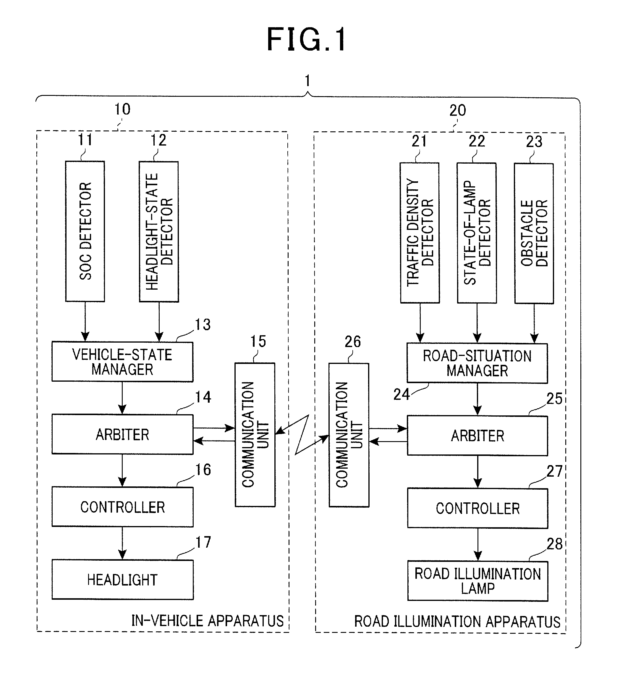
[0020]FIG. 1 shows a block diagram of a roadside-vehicle cooperative illumination system in accordance with one embodiment of the present invention. It is assumed in the present embodiment that a motor-driven vehicle is passing through an illumination range of a road illumination apparatus (or a road illuminator) 20 which is a roadside apparatus. In alternative embodiments, the motor-driven vehicle may be replaced with an engine-driven vehicle.

[0021]Referring to FIG. 1, the roadside-vehicle cooperative illumination system 1 includes an in-vehicle apparatus 10 mounted in the motor-driven vehicle, and a road illumination apparatus 20.

[0022]The motor-driven vehicle includes a motor (not shown) that drives the vehicle and a battery (not shown) that supplies electrical power to the headlight 17. The in-vehicle apparatus 10 of the...


PUM


Abstract

A roadside-vehicle cooperative illumination system in which a headlight of a vehicle and a road illumination lamp can be controlled cooperatively through communications between an in-vehicle apparatus and a roadside apparatus. For example, when power consumption of the headlight has to be reduced, an in-vehicle apparatus side arbiter transmits a request to the roadside apparatus for increase illumination of the road illumination lamp. A roadside apparatus side arbiter determines whether or not to accept the request from the in-vehicle apparatus, and a roadside apparatus side controller controls the road illumination lamp according to the determination of the roadside apparatus side arbiter. This enables the road illumination lamp to be controlled cooperatively so that illumination of the road illumination lamp can compensate for deficiencies in illumination of the headlight, which leads to enhancement of vehicle driver's convenience and ensuring of safety.

Description

CROSS-REFERENCE TO RELATED APPLICATION[0001]This application is based on and claims the benefit of priority from earlier Japanese Patent Application No. 2010-219389 filed Sep. 29, 2010, the description of which is incorporated herein by reference.BACKGROUND[0002]1. Technical Field[0003]This invention relates to a roadside-vehicle cooperative illumination system in which a headlight of a vehicle and a road illumination lamp are controlled cooperatively through communications between an in-vehicle apparatus and a roadside apparatus.[0004]2. Related Art[0005]A known road illumination system, as disclosed in Japanese Patent Application Publication No. 2002-305088, controls illumination of a road illuminator as a function of a traffic density so as to reduce power consumption of the road illuminator.[0006]The above disclosed road illumination system includes a road illuminator that illuminates a road, a service marker arranged at a position through which a vehicle that will travel within...

Claims


Application Information

Patent Timeline
IPC IPC(8): B60Q1/06H01K7/00
CPCB60Q1/1423B60Q2300/314B60Q2300/3321Y02B20/72B60Q2300/47B60Q2900/30H05B37/0272B60Q2300/42H05B47/155H05B47/19
Inventor HATTORI, YOUSUKEMORI, KATSUYUKICHIBA, KUNIHIKOGOTO, MASAHIRO
Owner DENSO CORP
Why Eureka
Try Eureka