Connection structure having guiding mechanism

Inactive Publication Date: 2012-03-29
SHUTTLE
View PDF5 Cites 8 Cited by
  • Summary
  • Abstract
  • Description
  • Claims
  • Application Information

AI Technical Summary

Benefits of technology

[0010]The object of the present invention is to provide a connection structure having guiding mechanism, which provides the guiding mechanism for users to perform the connection between the electronic device and the docking station rapidly and accurately.
[0012]Compared to the conventional art, the present invention has the advantages that once the status-indicating unit is aligned to the position-marking unit by a user, the female connector on the electronic device will be rapidly and accurately aligned to the male connector on the docking station. The user no longer has to stay close to the bottom side of the electronic device to see the female connector while performing the connection. Besides, the status-indicating unit emits light beam for alignment, which enables the possibility of performing the connection in a dark environment.

Problems solved by technology

However, conventional electronic devices 11 and docking stations 12 do not have any guiding mechanism for helping them connect with each other.
In addition, the female connector 110 is often located at the bottom side of the electronic device 11 where is not easy to view to the user when performing the mentioned connection.

Method used


Image

  • Connection structure having guiding mechanism
  • Connection structure having guiding mechanism
  • Connection structure having guiding mechanism

Examples


second embodiment

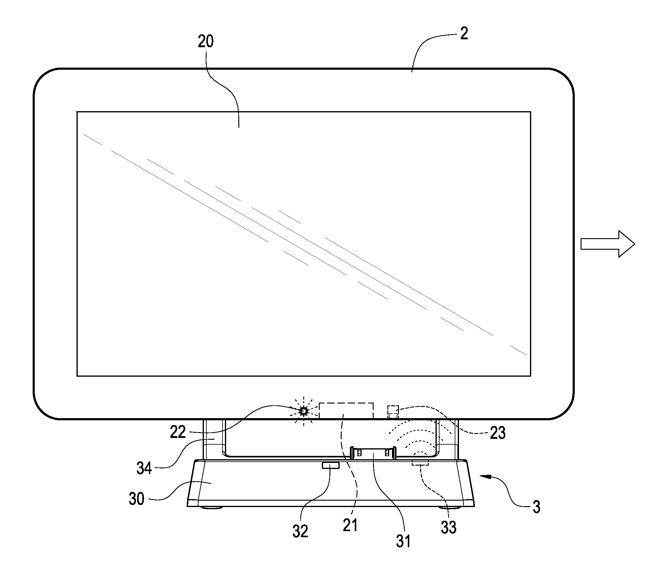
[0040]FIG. 4B shows a schematic view illustrating the position-marking unit according to the present invention. In this embodiment, the position-marking unit 32 can be a light-sensing strip arranged on the top side of the docking station 3. The docking station 3 further includes a connection-indicating unit 35 electrically connected to the male connector 31. The connection-indicating unit 35 can be a light-emitting diode. In this embodiment, the status-indicating unit 22 is a light-emitting diode or a laser source exposed out of the bottom side of the electronic device 2. Once the status-indicating unit 22 is activated to emit a light beam downwardly from the bottom side of the electronic device 2, and the electronic device 2 is move to a position where the status-indicating unit 22 is aligned to the position-marking unit 32, the position-marking unit 32 will receive and gather the light beam to inform the finish of the alignment between the female connector 21 and the male connecto...

third embodiment

[0041]FIG. 4C and FIG. 4D are respectively a schematic view and a sectional view of the position-making unit 32 according the present invention. In this embodiment, the position-marking unit 32 can be an L-shaped transparent tube arranged in the docking station 3 and exposed out of a top side and a front side of the docking station 3 as shown in FIG. 4D. The L-shaped transparent tube, for example, can be made of acrylic material. The status-indicating unit 22 is a light-emitting diode or a laser source exposed out of the bottom side of the electronic device 2. Once the sensing unit 23 senses the trigger element 33, the status-indicating unit 22 is activated by the sensing unit 23 to emit a light beam downwardly from the bottom side of the electronic device 2, and then the electronic device 2 is move to a position where the status-indicating unit 22 is aligned to the position-marking unit 32, the position-marking unit 32 will receive the light beam through the top side of the docking...

fourth embodiment

[0044]FIG. 6A shows the position-marking unit 32 according to the present invention. In this embodiment, the position-marking unit 32 on the electronic device 2 is a sign or a pattern as shown in FIG. 4A, which can be aligned to the status-indicating unit 22 in a bright environment.


PUM


Abstract

A connection structure having guiding mechanism includes a female connector, a sensing unit and a status-indicating unit arranged on an electronic device, and a male connector, a trigger element and a status-indicating unit arranged a docking station. While the electronic device is close to the docking station, the sensing unit will sense the trigger element and activate the status-indicating unit. Once the status-indicating unit is aligned to the position-marking unit by a user, the female connector will be aligned to the male connector.

Description

BACKGROUND OF THE INVENTION[0001]1. Field of the Invention[0002]The present invention relates to a connection structure, particularly relates to a connection structure having a guiding mechanism for user to perform connection processing rapidly and accurately.[0003]2. Description of Related Art[0004]The development of the semiconductor industry promotes the development of portable electronic products in recent years. Such portable electronic products like mobile phones, MP4 players, personal digital assistants (PDAs), and tablet PCs (such as Apple's iPad) are widely used in people's lives.[0005]The portable electronic devices not only can be carried by users, but also can be connected with computers as needed to be remotely controlled by the computers for sorting and updating data information. Besides, the most of the portable electronic devices having rechargeable batteries can be recharged by the power suppliers of the computers.[0006]FIG. 1 shows a schematic view illustrating the...

Claims


Application Information

Patent Timeline
IPC IPC(8): H05K7/00
CPCG06F1/1632H01R2201/06H01R13/7037
Inventor CHIEN, CHIH-HSIANGWENG, AN-SHENGCHEN, HIS-YUNLAI, HSIN-HUNGLEE, CHUN-TECHANG, CHENG-MINSHIH, CHAI-WEI
Owner SHUTTLE
Why Eureka
Try Eureka