Image forming apparatus

a technology of image forming apparatus and forming tube, which is applied in the direction of electrographic process apparatus, instruments, optics, etc., can solve problems such as image defects, and achieve the effect of preventing image defects

Inactive Publication Date: 2012-03-29
OKI DATA CORP
View PDF3 Cites 8 Cited by
  • Summary
  • Abstract
  • Description
  • Claims
  • Application Information

AI Technical Summary

Benefits of technology

[0005]In an aspect of the present invention, it is intended to provide an image forming apparatus capable of preventing image defects caused by transfer scattering or the like.

Problems solved by technology

Such an electrical discharge may cause transfer scattering (i.e., scattering of toner), and therefore image defects may occur.

Method used


Image

  • Image forming apparatus
  • Image forming apparatus
  • Image forming apparatus

Examples


first embodiment

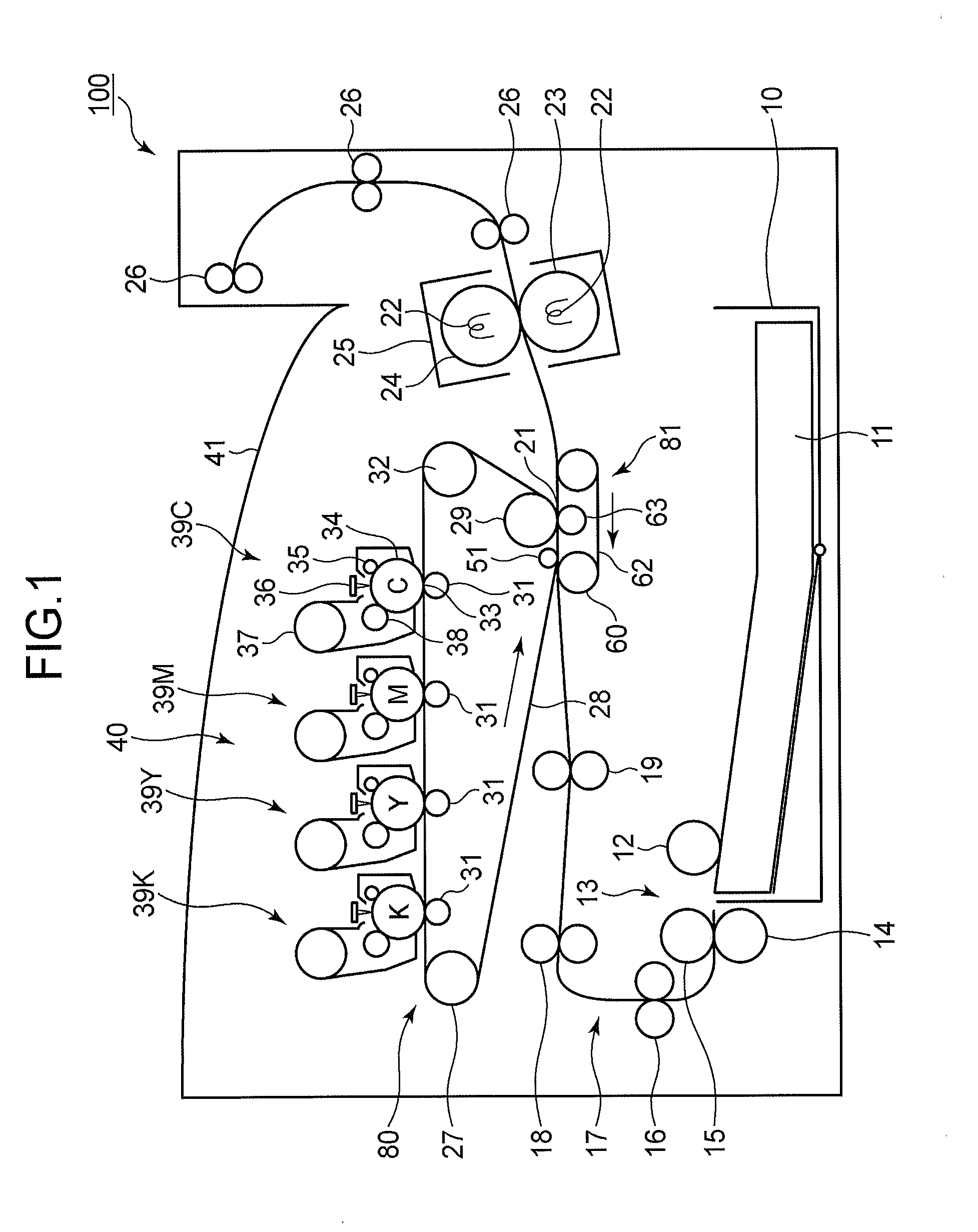
[0029]FIG. 1 is a schematic side view showing a configuration of an image forming apparatus 100 according to the first embodiment of the present invention.

[0030]The image forming apparatus 100 is configured as, for example, an electrophotographic printer. The image forming apparatus 100 includes a medium tray 10 in which recording media (i.e., media) 11 such as printing sheets are stored. A medium feeding portion 13 is provided on a feeding side (i.e., left side in FIG. 1) of the medium tray 10. The medium feeding portion 13 is configured to feed the recording medium 11 one by one out of the medium tray 10. The medium feeding portion 13 includes a pickup roller 12 that contacts the topmost recording medium 11 lifted to a predetermined height. The medium feeding portion 13 further includes a feeding roller 15 and a retard roller 14 for separately feeding the recording medium 11 picked up by the pickup roller 12.

[0031]A medium conveying portion 17 is provided on a downstream side of t...

second embodiment

[0116]Next, the second embodiment of the present invention will be described.

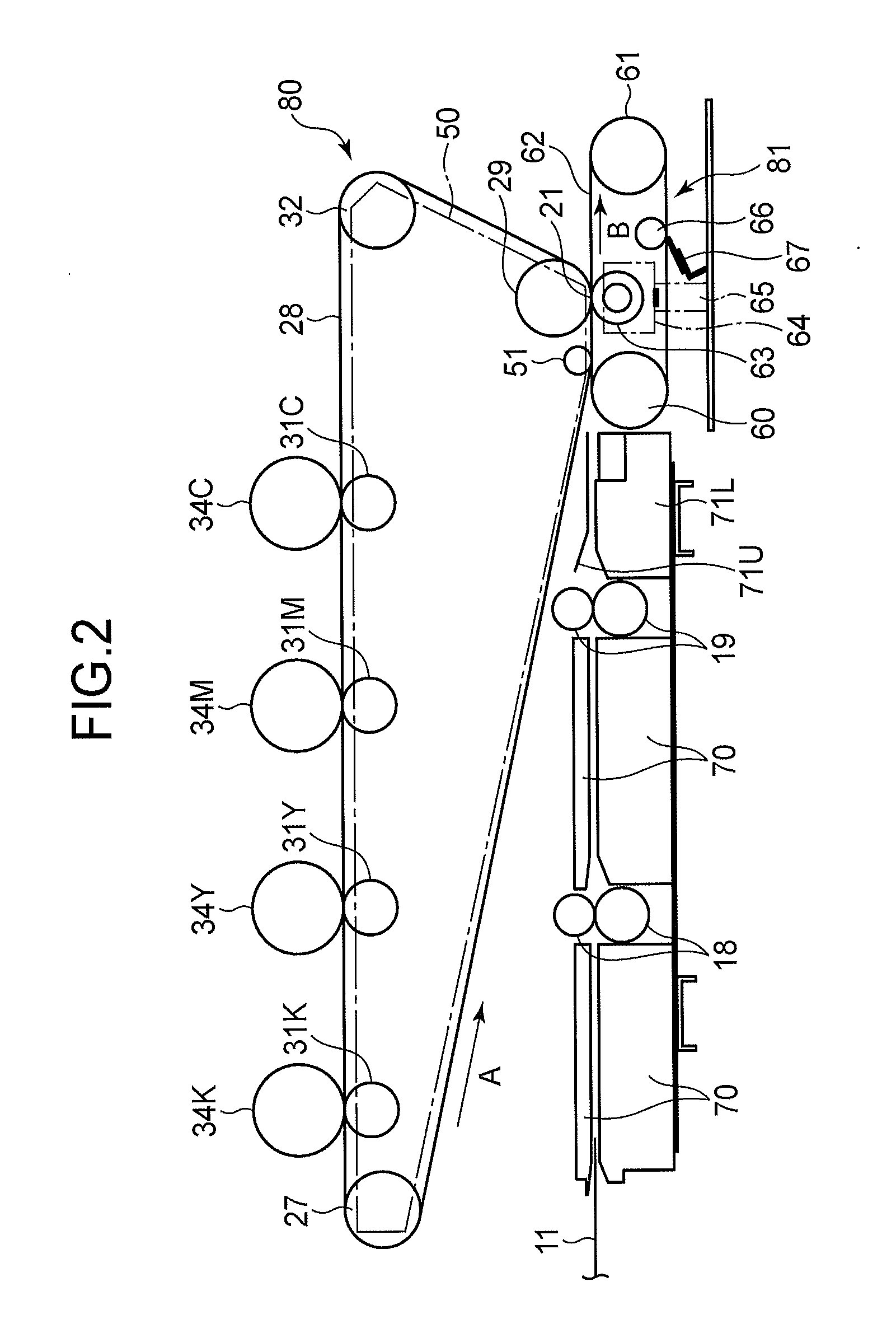
[0117]The second embodiment is different from the first embodiment in a configuration of a transfer portion.

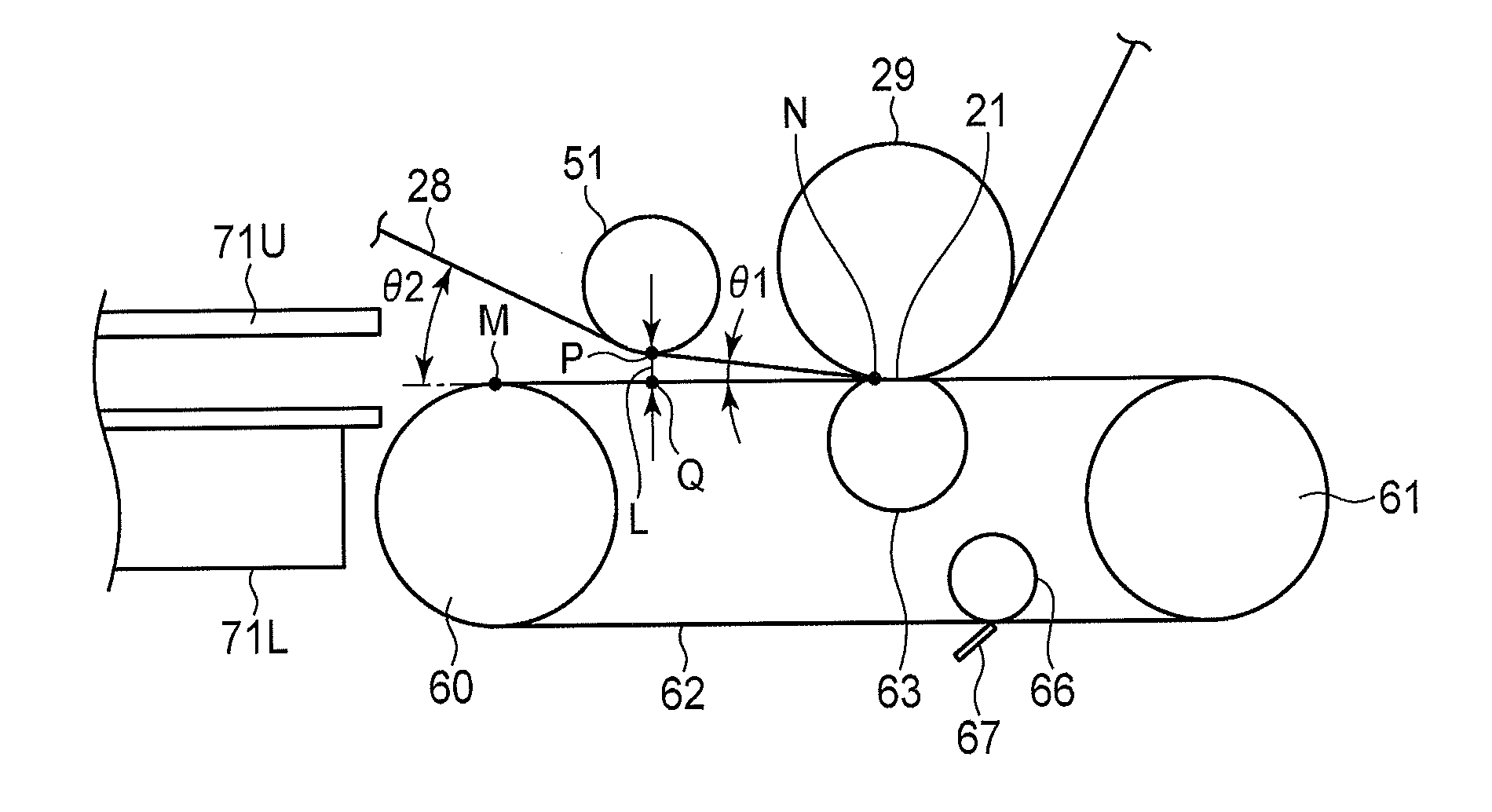
[0118]FIG. 11 is a schematic side view showing a transfer portion of an image forming apparatus according to the second embodiment. FIG. 12 is a perspective view showing a secondary transfer portion according to the second embodiment. FIG. 13 is a schematic side view showing a configuration around the secondary transfer portion 21. FIG. 14 is a schematic side view showing a gap adjusting portion according to the second embodiment. Components that are the same as those of the first embodiment are assigned the same reference numerals.

[0119]As shown in FIG. 11, a transfer portion of the second embodiment includes a transfer belt unit 80 and a conveying belt unit 81 as described in the first embodiment. Further, the transfer portion of the second embodiment includes a thickness sensor 75 as a medium thick...


PUM


Abstract

An image forming apparatus includes a primary transfer body that bears a developer image, a secondary transfer portion for transferring the developer image from the primary transfer body to a medium, and an introduction portion provided on an upstream side of the secondary transfer portion in a conveying direction of the medium. The introduction portion introduces the primary transfer portion and the medium toward the secondary transfer portion. The introduction portion has a gap having a predetermined distance therebetween.

Description

BACKGROUND OF THE INVENTION[0001]The present invention relates to an image forming apparatus that forms an image on a medium.[0002]In a conventional image forming apparatus, a toner image is formed by an image forming portion, and is transferred to a belt-shaped intermediate transfer body at a primary transfer portion. Then, at a secondary transfer portion, the intermediate transfer body contacts a recording medium conveyed by a conveying unit, and the toner image is transferred to the recording medium by Coulomb force (see, Patent Document No. 1).[0003]Patent Document No. 1: Japanese Laid-open Patent Publication No. 2010-134141 (paragraphs 0013-0019, FIG. 1)[0004]However, in the conventional image forming apparatus, when the toner image is transferred from the intermediate transfer body to the recording medium at the secondary transfer portion, an electrical discharge may occur between the intermediate transfer body (bearing the toner image) and the recording medium. Such an electr...

Claims


Application Information

Patent Timeline
Patent Type & Authority Applications(United States)
IPC IPC(8): G03G15/16
CPCG03G15/161G03G15/6561G03G15/1615G03G15/6558
Inventor KASEDA, SHINYA
Owner OKI DATA CORP
Why Eureka
Try Eureka