Developing device

a technology of developing device and development distance, which is applied in the direction of electrographic process apparatus, instruments, optics, etc., can solve the problems of non-uniformity of image density or increase of mechanical deposition power of toner, and affecting the development speed. , to achieve the effect of preventing deterioration and prolonging the distance between n1 and n1

Inactive Publication Date: 2005-11-03
CANON KK
View PDF19 Cites 9 Cited by
  • Summary
  • Abstract
  • Description
  • Claims
  • Application Information

AI Technical Summary

Benefits of technology

[0024] It has in considered to extend the distance between N1 and N3 poles which are repelling poles. These, however results in the N3 pole approaches to the S2 pole which is the developing pole. This causes stagnation of the developer at a positioned between S2 pole and N3 pole when the result of toner scattering due to the flappering action of the chains of the developer. This is remarkable when the speed is high.
[0025] Accordingly, it is a principal object of the present invention to provide a developing device and an image forming apparatus with which image defects attributable to deterioration of the developer is prevented. It is another object of the present invention to provide a developing device and an image forming apparatus in which carryover of the developer is prevented.

Problems solved by technology

However, the conventional vertical arrangement type developing device 103 involves a problem.
When such deterioration of the developer occurs, the triboelectric charge amount of the toner varies with elapses of time with the result of variation in the development property of the toner which leads to non-uniformity of the image density or increase of the mechanical deposition power of the toner relative to the magnetic carrier particles or to the photosensitive drum.
This may result in local defects of the toner, and therefore, the image quality is deteriorating.

Method used


Image

  • Developing device
  • Developing device
  • Developing device

Examples


embodiment 1

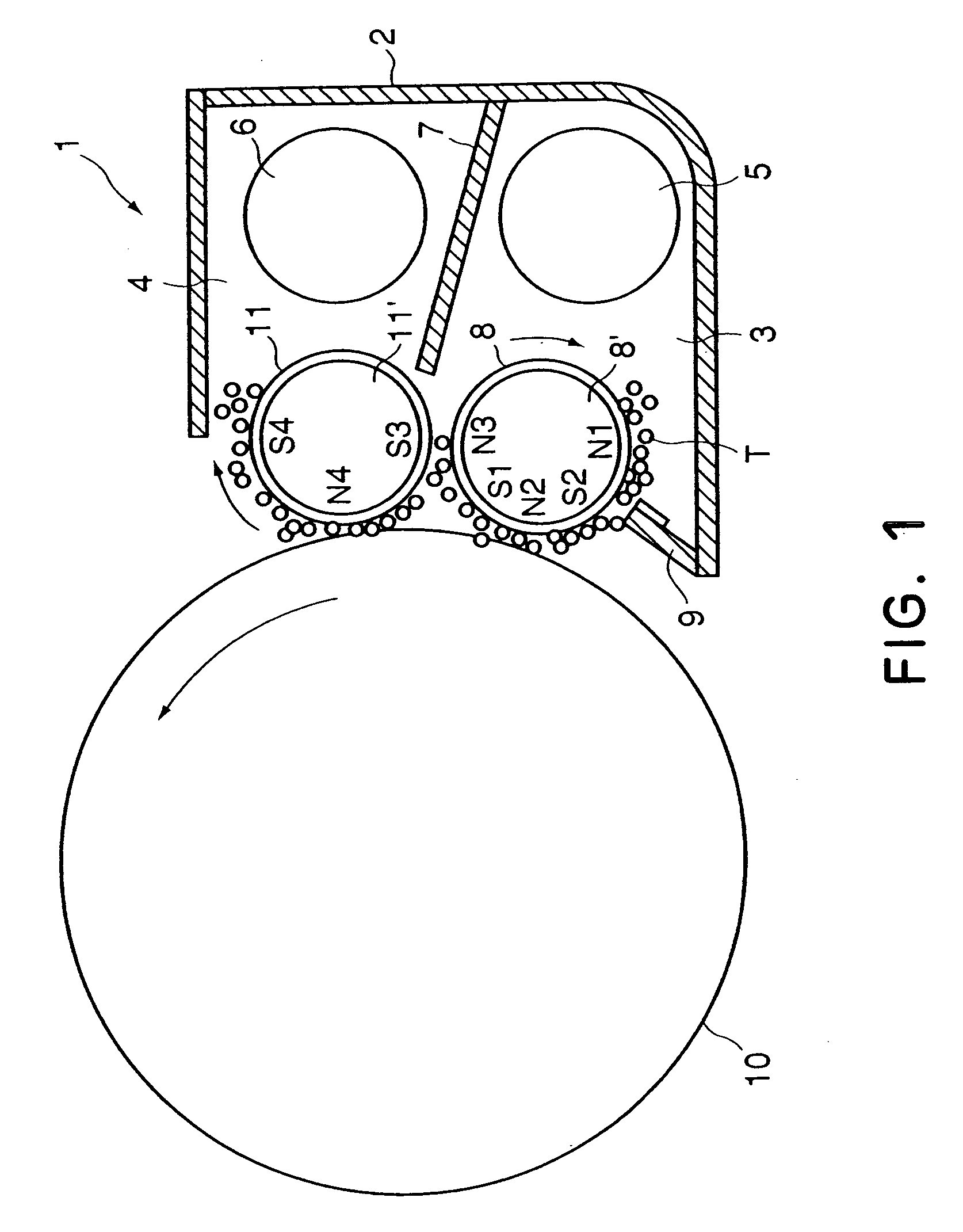
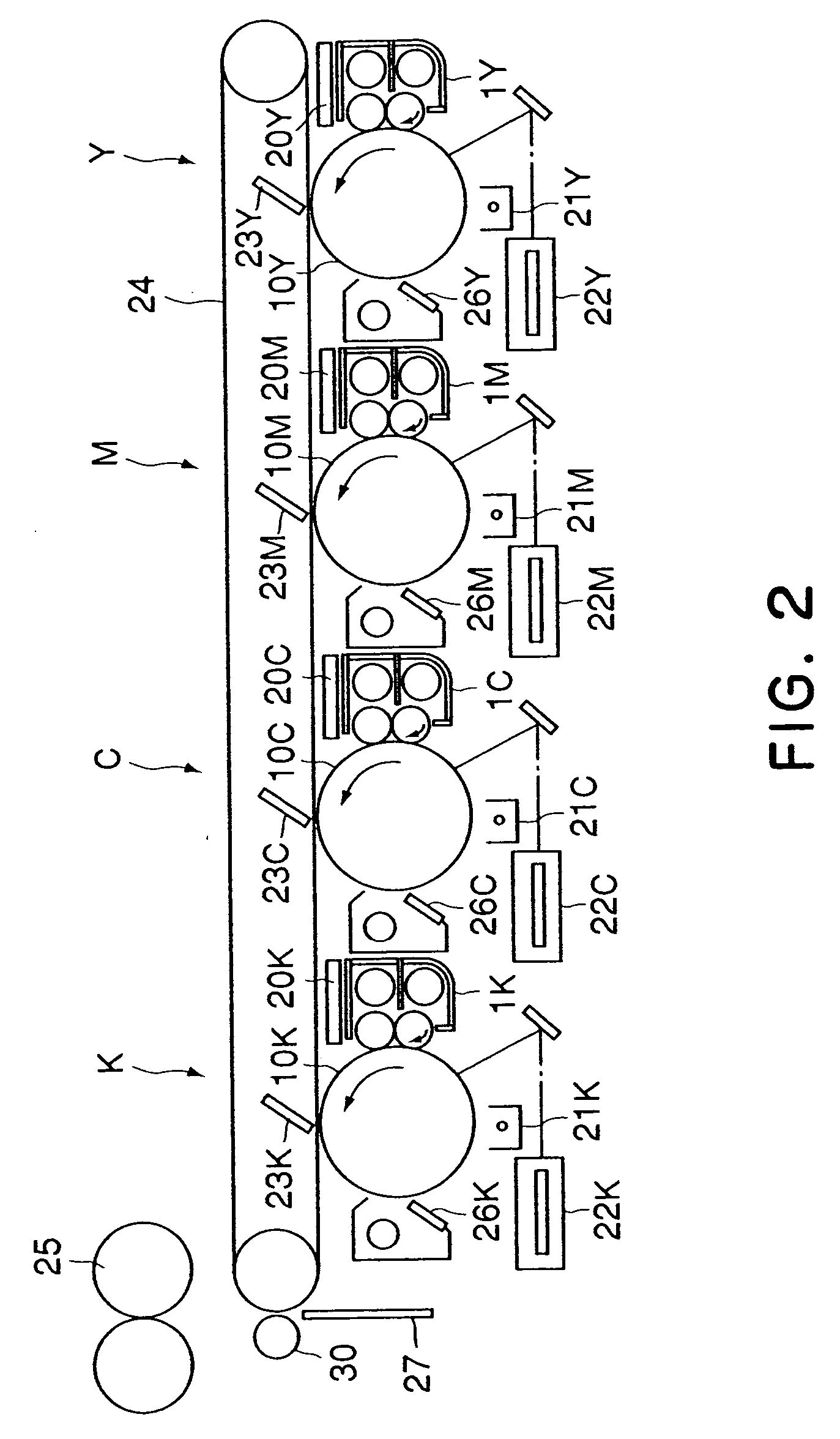
[0043]FIG. 1 shows a positional relation of the developing device 1 relative to image bearing member (photosensitive drum) 10 in each of Y, M, C, K image forming stations in a full-color image forming apparatus as shown in FIG. 2. The Y, M, C, K image forming stations have substantially the same structure, and they form yellow (Y), magenta (M), cyan (C) and black (K) images, respectively in a full-color image forming operation. In the following descriptions, when reference is made to “developing device 1”, it applies to a developing device in each of developing device 1Y, developing device 1M, developing device 1C and developing device 1K in the Y, M, C, K image forming stations..

[0044] Referring to FIG. 2, the operations of the entire image forming apparatus will be described.

[0045] The photosensitive drum 10 (image bearing member) is rotatably provided in image forming apparatus, the photosensitive drum 10 is uniformly charged by a primary charger 21 and is then exposed to light...

embodiment 2

[0067] Referring to FIG. 5 a developing device according to Embodiment 2 will be described.

[0068] The developing device of this embodiment is similar to that of Embodiment 1. However, in the developing device 100 of this embodiment, the regulating blade 9 is opposed to a neighborhood of a first magnetic pole N1 which is a downstream side magnetic pole of the first and second magnetic poles N1, N3 which are provided in the first developing sleeve and which form the repelling magnetic field with respect to the rotational direction of the developing sleeve 8, by which the regulation of the layer thickness for the developer is effected simultaneously with taking the developer up.

[0069] This arrangement per se is known as means with which the developing device torque can be significantly reduced as disclosed in Japanese Laid-open Patent Application Hei 11-194617. However, if this is used with a single developing sleeve structure or with the horizontal arrangement, the developer stagnat...

embodiment 3

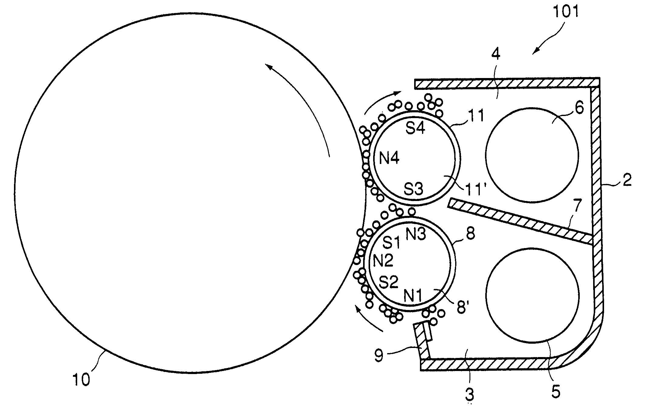
[0072] Referring to FIG. 6, Embodiment 3 of this invention will be described. FIG. 6 is and axial sectional view of the developing device 101 according to this embodiment.

[0073] The developing device of this embodiment has substantially the similar structure to the developing device 1 of Embodiment 1. However, in this embodiment, there is provided a discharge opening 12, in the outer wall adjacent a most downstream portion of the developer chamber 3 wall, for discharged the developer when the height of the surface level of the developer exceeds a predetermined level (indicated by g in the Figure).

[0074] When the developer T said by the feeding screw 5 in the developer chamber 3 is not taken up on the first developing sleeve 8 and is accumulated in the developer stagnation portion at the most downstream portion of the developer chamber 3, the surface level of the power of the developer rises. Even in such a case, the developer is automatically discharged through the developer disch...


PUM


Abstract

A developing apparatus includes a developing container for containing a developer comprising toner and a carrier, said developing container is partitioned into a first chamber and a second chamber constituting a circulation path of the developer; a first developing rotatable member, provided in said first chamber, for developing an electrostatic image formed on the image bearing member with the developer in said first chamber; a regulating member for regulating a layer thickness of the developer on said first developing rotatable member; first magnetic pole and second magnetic pole, disposed in said first developing rotatable member in order named in a rotational direction of said first developing rotatable member, said first magnetic pole and second magnetic pole being defective to form a repelling magnetic field; a second developing rotatable member, disposed in said second chamber, for developing the the electrostatic image formed on the image bearing member with the developer magnetically received from said first developing rotatable member; wherein said regulating member is disposed at a position substantially opposed to said second magnetic pole.

Description

FIELD OF THE INVENTION AND RELATED ART [0001] The present invention relates to a developing device usable with a copying machine, a printer, facsimile machine or the like of an electrophotographic type or electrostatic recording type. [0002] In an image forming apparatus such as a copying machine or the like using an electrophotographic type process, an electrostatic latent image formed on an image bearing member such as a photosensitive drum is visualized by depositing a developer. Among conventional developing devices for such a developing operations, there is a type using a two component developer comprising toner particles and carrier particles. Referring first to FIG. 12, there is shown such a developing device. In a developing device 102 using the two component developer, as shown in FIG. 12, the two component developer T is fed while being stirred. In many of the developing devices, two feeding screws 5, namely, a first feeding screw 5 and a second feeding screw 6 which are c...

Claims


Application Information

Patent Timeline
Patent Type & Authority Applications(United States)
IPC IPC(8): G03G15/09
CPCG03G15/0893G03G15/0921G03G2215/0822G03G2215/0648G03G2215/0609
Inventor HIROBE, FUMITAKEHIBINO, MASARUSAKAMAKI, TOMOYUKI
Owner CANON KK
Why Eureka
Try Eureka