Image forming apparatus

Inactive Publication Date: 2005-10-20
CANON KK
View PDF7 Cites 8 Cited by
  • Summary
  • Abstract
  • Description
  • Claims
  • Application Information

AI Technical Summary

Benefits of technology

[0009] Another object of the present invention is to provide an image forming apparatus capable of preventing an insufficient transfer current and disorder of toner on a toner image carrying member or a recording material due to discharge or the like, thereby to prevent image defects.

Problems solved by technology

However, in the above described conventional image forming apparatuses, in the transfer step, a transfer current generated by a voltage applied to the transfer means considerably flows into a grounding portion through the stretching member for the recording material carrying member or that for the intermediary transfer belt or through the charge removal needle disposed on the downstream side of the transfer means, so that it becomes difficult to appropriately transfer the toner image carried on the image bearing member in some cases.
Further, in some cases, when a large amount of electric charge is removed by a charge removing member, an electric charge is not supplied in an amount corresponding to that of electric charge to be removed,. so that a resultant transfer current becomes insufficient.

Method used


Image

  • Image forming apparatus
  • Image forming apparatus
  • Image forming apparatus

Examples


first embodiment

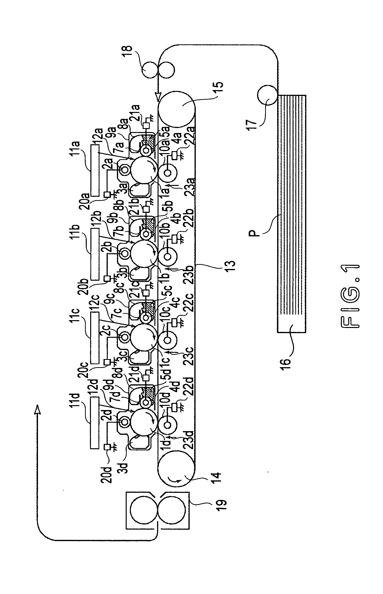
[0032] Figure shows a schematic structure of the image forming apparatus according to the present invention.

[0033] In this embodiment, a yellow (Y) toner image is formed at a first station, a magenta (M) toner image is formed at a second station, a cyan (C) toner image is formed at a third station, and a black (K) toner image is formed at a fourth station.

[0034] At the first station, an integral-type process cartridge 9a is constituted by an OPC photosensitive drum 1a as an image bearing member; a charge roller 2a as a charging means; a cleaning unit 3a for cleaning residual toner remaining on the photosensitive drum 1a; and a developing unit 8a, as a developing means, including a developing sleeve 4a, a nonmagnetic one-component developer 5a, and a developer application blade 7a.

[0035] Further, an exposure means 11a is constituted by a scanner unit for effecting scanning with laser light through a polygonal mirror, or an LED array, and the surface of the photosensitive drum is i...

second embodiment

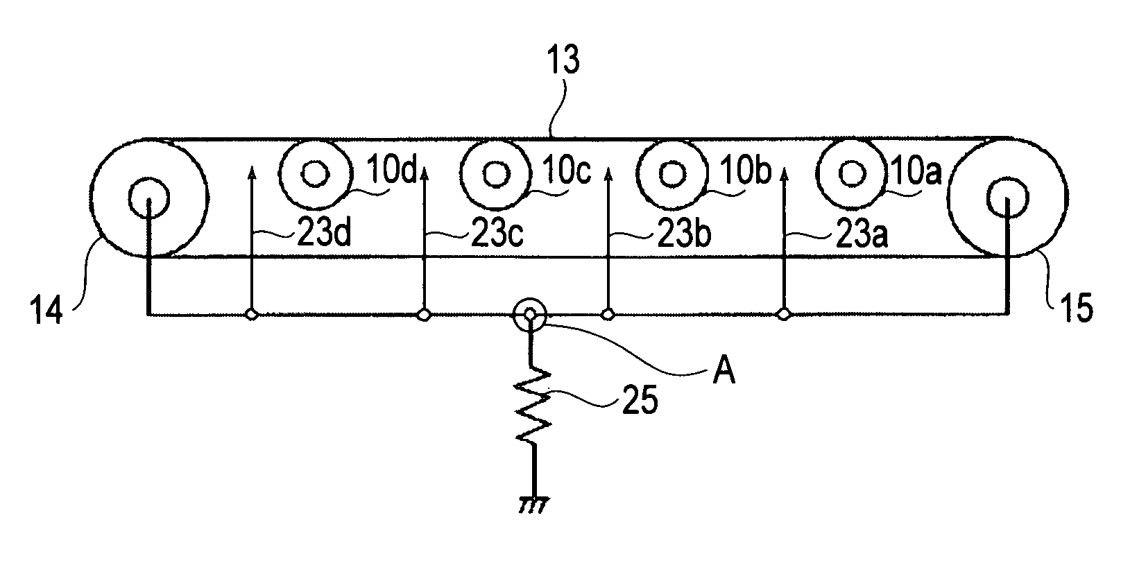
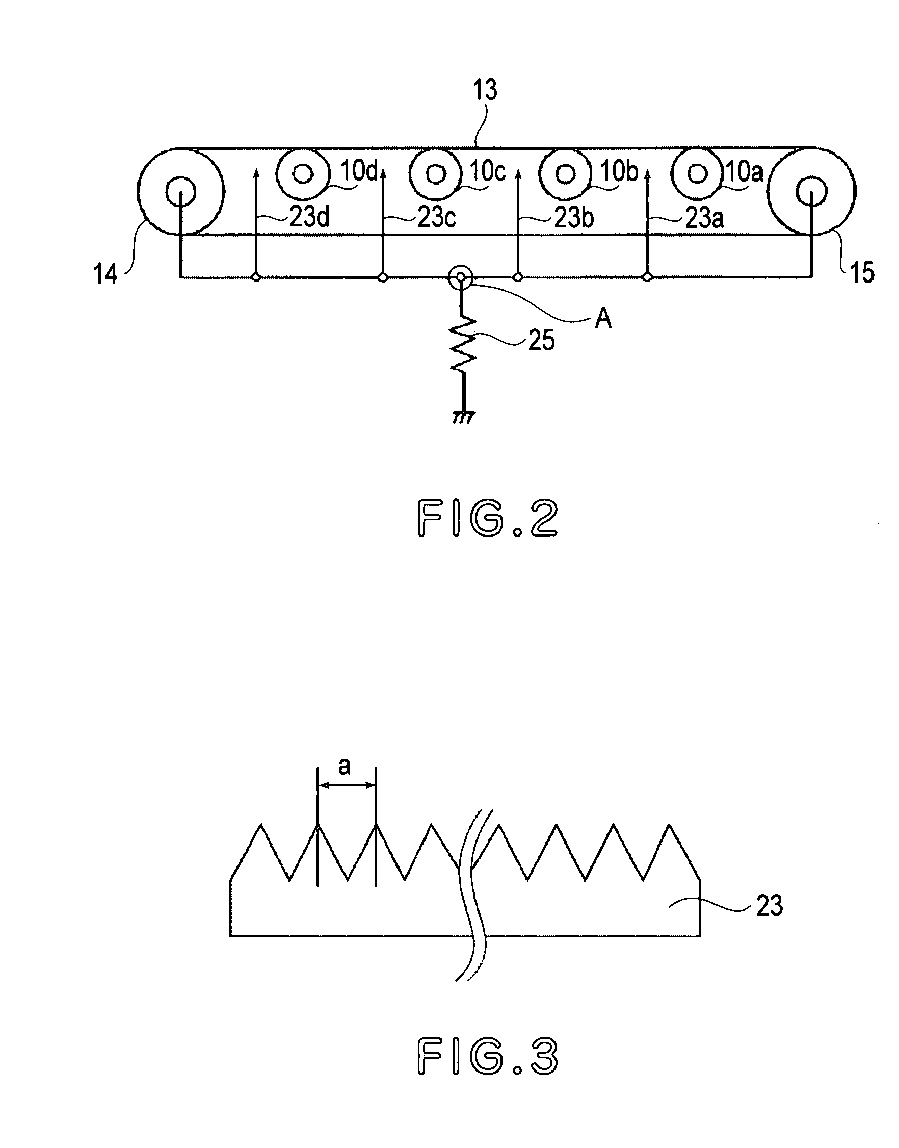
[0064] In this embodiment, an image forming apparatus is prepared in the same manner as in First Embodiment except that all the charge removing members consisting of the drive roller 14, the tension roller 15, and the charge removal needles 23a-23d are electrically connected with each other and grounded through a constant-voltage element 26 as shown in FIG. 6 (instead of the resistor 25 shown in FIG. 5 in First Embodiment).

[0065] As the constant-voltage element 26, it is possible to use a varistor, a zener diode, etc., which have a voltage in the range of 50 V to 1 kV. In this embodiment, a varistor having a varistor voltage of 500 V is used.

[0066] The drive roller 14, the tension roller 15, and the charge removal needles 23a-23d are grounded through the varistor 26.

[0067] Next, an action in this embodiment will be described.

[0068] In the high temperature / high humidity environment, the transfer belt 13 and the recording material P take up moisture to lower an electrical resistan...

third embodiment

[0071] An image forming apparatus using an intermediary transfer belt will be described with reference to FIG. 7.

[0072] Hereinbelow, an image forming operation will be described in detail.

[0073] All the actions (functions), in an image forming process, of photosensitive drums 1a-1d, charge rollers 2a-2d as charging means, exposure means 11a-11d, developing apparatuses 8a-8d, and cleaning means 3a-3d for the photosensitive drums 1a-1d used in this embodiment are similar to those in First Embodiment described above. On the surfaces of the photosensitive drums 1a-1d, toner images are formed as described above specifically.

[0074] On the other hand, an intermediary transfer belt 80 as a toner image carrying member is disposed so as to contact all the photosensitive drums 1a-1d.

[0075] The intermediary transfer belt 80 is supported by three rollers, as stretching members, including a secondary-transfer opposite roller 86, a drive roller 14, and a tension roller 15, thus being held unde...


PUM


Abstract

An image forming apparatus includes a recording material carrying member which is movable while carrying a recording material, a first charge removing member for removing an electric charge from the recording material carrying member, and a second charge removing member for removing an electric charge from the recording material carrying member. The first and the second charge removing member are electrically connected with each other at a predetermined point where the first and second chrge removing members are electrically grounded through an electric element.

Description

FIELD OF THE INVENTION AND RELATED ART [0001] The present invention relates to an image forming apparatus, utilizing electrophotographic recording process, such as a laser printer, a copying machine, a facsimile apparatus, etc. [0002] In an image forming apparatus, using an electrophotographic process, such as a copying machine or a printer, such a transfer step that a toner image as a developer image carried on a photosensitive member as an image bearing member is electrostatically transferred onto a recording material carried on a recording material carrying belt (member) or an intermediary transfer belt (member) by the action of an electric field, has conventionally been performed. For this reason, in the image forming apparatus provided with the recording material carrying belt or the intermediary transfer belt, a voltage application means for applying a voltage, required for the transfer step, to a transfer means is provided. As an example thereof, a contact transfer member con...

Claims


Application Information

Patent Timeline
IPC IPC(8): G03G15/00B65H5/00G03G15/14G03G15/16
CPCG03G15/161G03G2215/1623G03G2215/1614G03G15/1645H02G3/0418
Inventor SHIMURA, MASARUKANARI, KENJI
Owner CANON KK
Why Eureka
Try Eureka