Image forming apparatus

Active Publication Date: 2020-10-01
FUJIFILM BUSINESS INNOVATION CORP
View PDF0 Cites 0 Cited by
  • Summary
  • Abstract
  • Description
  • Claims
  • Application Information

AI Technical Summary

Benefits of technology

[0010]Aspects of non-limiting embodiments of the present disclosure relate to providing an image forming apparatus that has only o

Problems solved by technology

If an image holding unit is stopped while a developing bias voltage is applied to the developing unit, particularly, in a high-temperature, high-humidity environment, an area of the image holding unit facing the developing unit may be charged under the influence of the de

Method used


Image

  • Image forming apparatus
  • Image forming apparatus
  • Image forming apparatus

Examples


Embodiment Construction

[0023]Hereinafter, exemplary embodiments according to the present disclosure will be described.

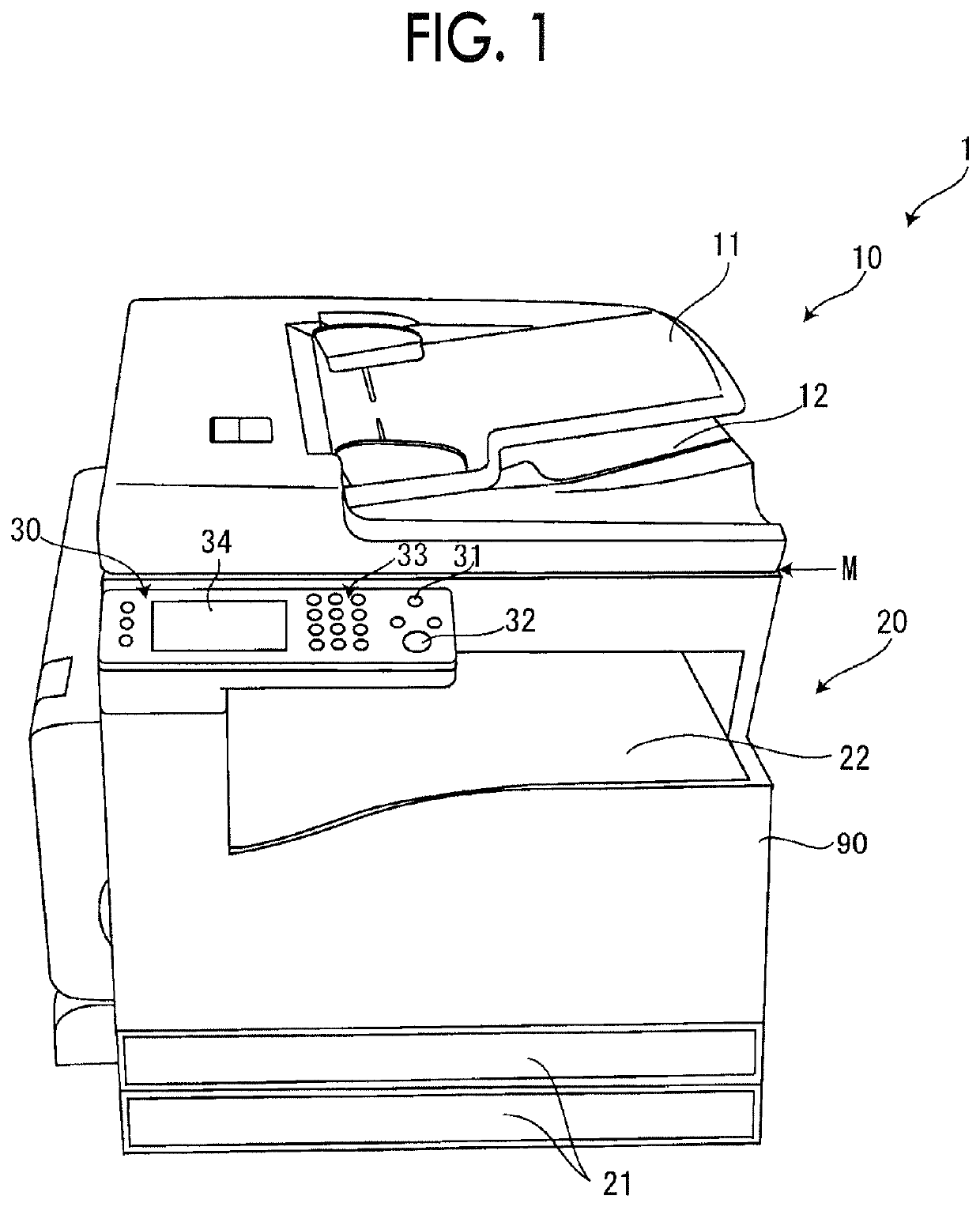
[0024]FIG. 1 is an external perspective view of an image forming apparatus as a first exemplary embodiment of the present disclosure;

[0025]The image forming apparatus 1 includes an apparatus casing 90, and includes a scanner 10 placed on the apparatus casing 90 and a printer 20 configured in the apparatus casing 90.

[0026]The scanner 10 is an apparatus which reads an image drawn on a document and generates an image signal. The printer 20 is an apparatus which prints out an image based on an image signal on paper by a so-called electrophotographic process.

[0027]The scanner 10 includes a document tray 11 and a document output tray 12. When a start button 32 is pressed in a state of documents being stacked on the document tray 11, the documents are sequentially fed and read one by one and discharged onto the document output tray 12. In addition, the scanner 10 is provided with a hinge (not ill...


PUM


Abstract

An image forming apparatus includes: a plurality of image holding units that include first and second image holding units and on which toner images are formed through developing while the image holding units rotate; a plurality of developing units that respectively face the plurality of image holding units and develop an electrostatic latent image on each of the plurality of image holding units with toner under a developing bias voltage applied to each developing unit; a power supply unit that applies a developing bias voltage to the plurality of developing units, and is common to the plurality of image holding units; an intermediate transfer unit that receives transfer of a toner image from the plurality of image holding units and transfers the toner image to a transfer receiver while circulating in a circulation path including a moving path along the plurality of image holding units, the intermediate transfer unit having first and second modes, wherein in the first mode, the intermediate transfer unit receives transfer of a toner image from the plurality of image holding units, and in the second mode, the intermediate transfer unit is separated from the second image holding unit other than the first image holding unit and receives transfer of a toner image from the first image holding unit; and a driving unit that drives rotation of the plurality of image holding units, wherein in the second mode, the driving unit drives the second image holding unit so as to temporally change a position at which the second image holding unit faces the developing unit.

Description

CROSS-REFERENCE TO RELATED APPLICATIONS[0001]This application is based on and claims priority under 35 USC 119 from Japanese Patent Application No. 2019-069576 filed Apr. 1, 2019.BACKGROUND(i) Technical Field[0002]The present disclosure relates to an image forming apparatus.(ii) Related Art[0003]One of known image forming apparatuses is what is called a tandem type. Such a tandem type image forming apparatus includes plural image holding units and plural developing units that respectively face the plural image holding units and develop an electrostatic latent image on each of the plural image holding units with toner. The electrostatic latent images on the plural image holding units are firstly transferred onto an intermediate transfer belt and secondarily transferred onto paper.[0004]One of tandem type image forming apparatuses is configured to switch between a color image forming mode and a monochrome image forming mode. Such a mode switching type image forming apparatus has measu...

Claims


Application Information

Patent Timeline
IPC IPC(8): G03G21/20G03G15/06G03G15/16
CPCG03G15/065G03G15/1605G03G21/203
Inventor OKUNO, TAICHIRO
Owner FUJIFILM BUSINESS INNOVATION CORP
Why Eureka
Try Eureka